Cable connector with shielded termination area

a cable connector and termination area technology, applied in the direction of coupling device connection, coupling protective earth/shielding arrangement, electrical apparatus, etc., can solve the problems of increased crosstalk possibility, increased potential for signal-disrupting crosstalk, and increased unused area, so as to achieve simple standard construction and facilitate assembly

Inactive Publication Date: 2005-10-18
MOLEX INC
View PDF17 Cites 78 Cited by
  • Summary
  • Abstract
  • Description
  • Claims
  • Application Information

AI Technical Summary

Benefits of technology

[0007]Accordingly, it is a general object of the present invention to provide an improved grounding shield for use with wafer connector modules which has a simple standard construction, and permits ease of assembly.
[0008]Another object of the present invention is to provide a grounding shield for use with wafer connectors which does not increase the connector size or result in a decrease of pin density in an opposing, mating connector.
[0009]Yet another object of the present invention is to provide a grounding shield of singular configuration that may be easily varied, as in its width, to accommodate as many grounding paths as desired.
[0011]Yet one more object of the present invention is to provide a high-density cable connector with a grounding shield having a length sufficient to extend over a termination area of the signal contacts of the connector, the shield having a plurality of openings formed therein aligned with the signal contacts which define windows opening through the shield which facilitate the termination of the signal contacts of the connector, without altering the configuration of the connector.

Problems solved by technology

Structures for attaining these aims are known in the art, but tend to be bulky and require additional, valuable, empty unused area.
At higher frequencies that are used for data transmission, the potential for signal-disrupting crosstalk increases greatly and unless the entire signal contacts are shielded, the possibility of occurrence of crosstalk increases.

Method used


Image

  • Cable connector with shielded termination area
  • Cable connector with shielded termination area
  • Cable connector with shielded termination area

Examples


Embodiment Construction

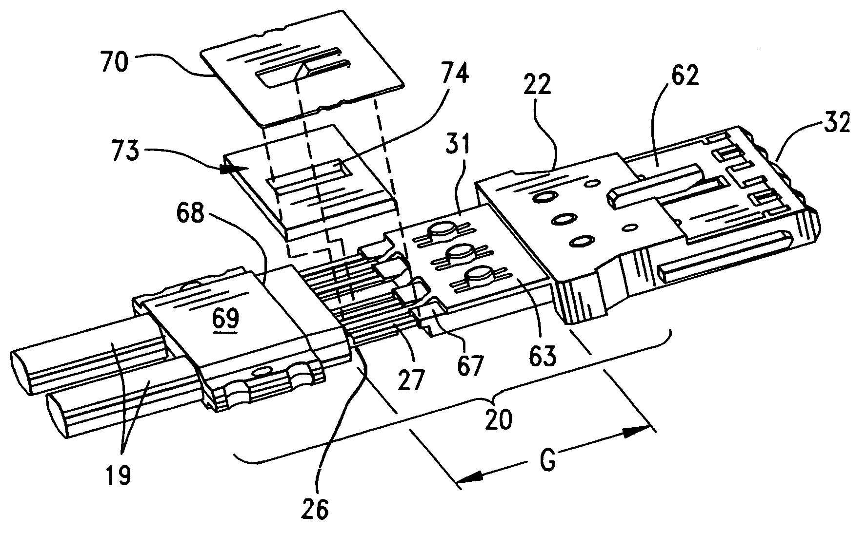
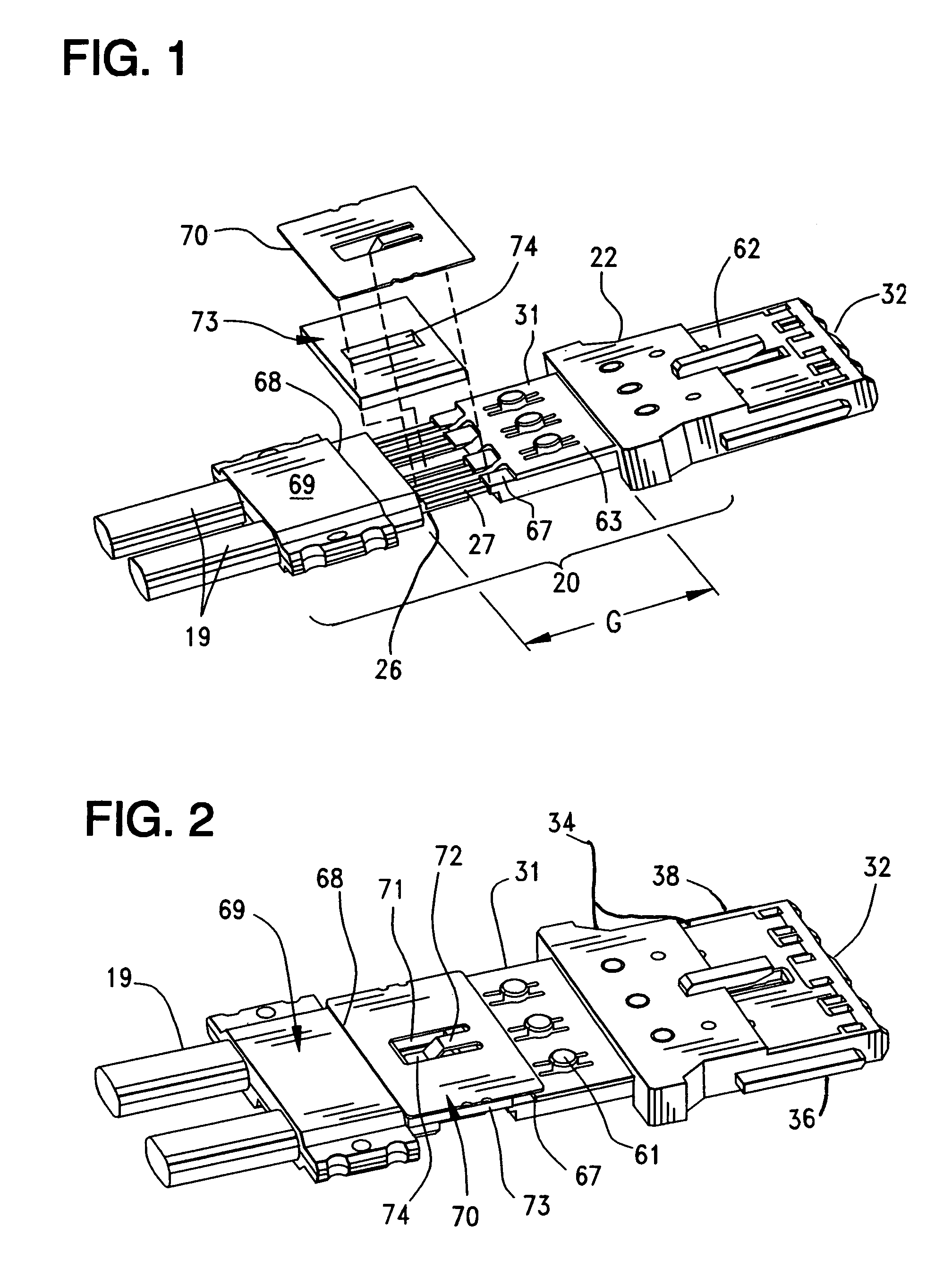
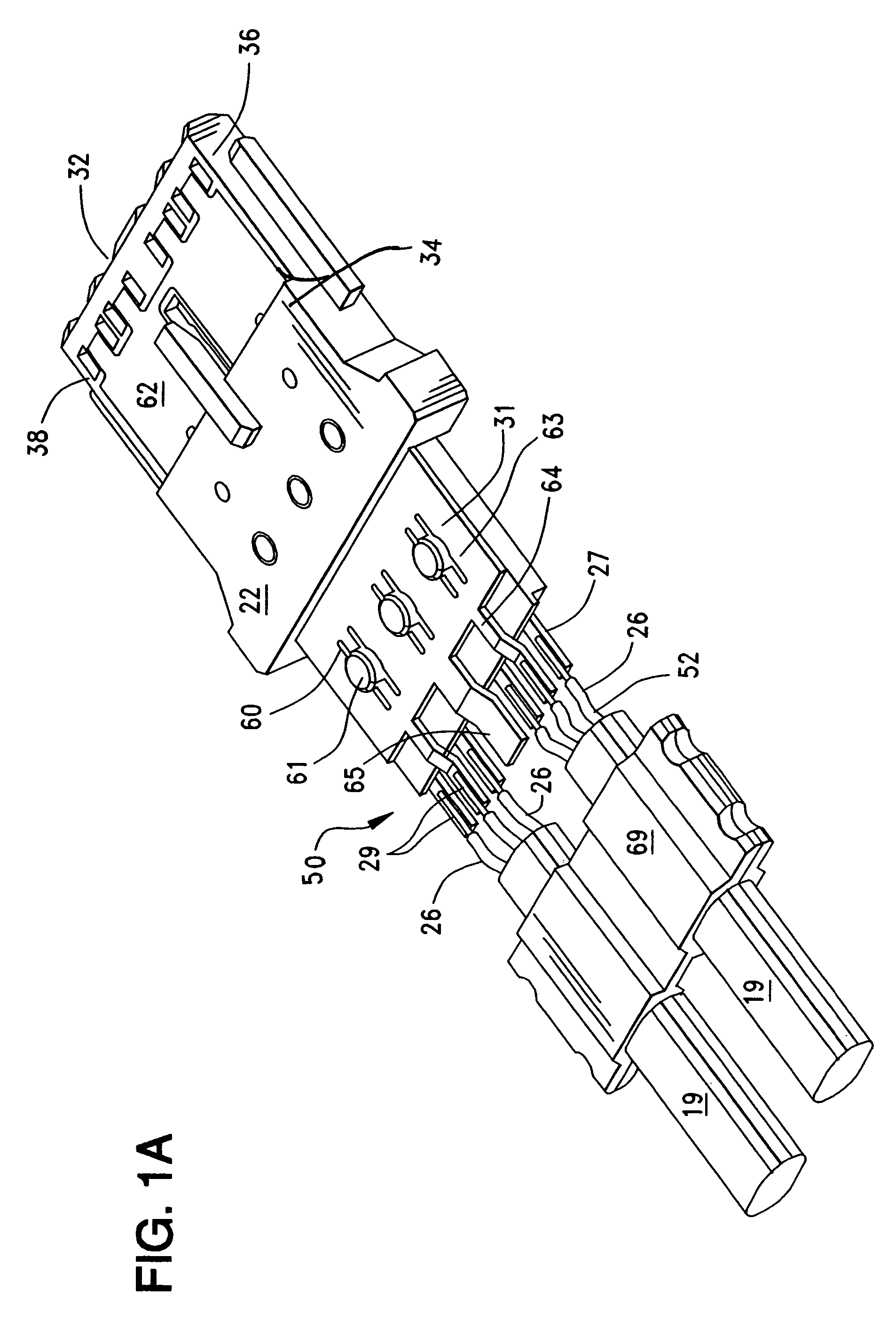
[0033]FIGS. 1 and 1A illustrate an electrical connector element, or module 20, which has a relatively thin profile and such a connector is commonly termed a “wafer” connector in the art. The connector module 20, as is known in the art, has a primary housing 22 formed from an electrically insulative material which houses a plurality of conductive terminals 24. These terminals 24 extend through the connector primary housing 22 in order to provide conductive paths between individual wires 26, that are arranged near along a rear end of the primary housing 22. The wires 26 are held within a 19 that may have (not shown) an inner braided wire shield that encompasses the two signal wires 26. Typically, one such cable 19 will contain two individual signal wires 26. The front end 32 of the primary housing 22 (and the module 20) that is adapted for insertion into an opposing backplane-style connector, such as a pin header (not shown) that includes a plurality of conductive pins arranged in row...


PUM


Abstract

A cable connector is provided that has a connector housing that is thin and takes the form of a wafer. Terminals are held within the housing and termination portions extend lengthwise from the terminals. The termination portions extend out from the housing for terminating bare conductors of signal wires to them. A grounding shield is provided that extends over the signal terminals from their contact portions at the front end of the connector to their rear termination portions. The grounding shield thereby provided a ground extent over the termination area that increases the electrical affinity of the signal wires to the grounding shield so as to reduce crosstalk and noise during operation at high frequencies. In one embodiment, the grounding shield includes a separate extension that is connected to the base grounding shield. In another embodiment, the grounding shield has a length sufficient to extend over the termination area.

Description

REFERENCE TO RELATED APPLICATIONS[0001]This application claims priority of U.S. Provisional Patent Application No. 60 / 437,044, filed Dec. 30, 2002.BACKGROUND OF THE INVENTION[0002]The present invention relates generally to connectors used in high-speed and high-density cable connector assemblies, and more particularly to a cable connector that has an improved grounding shield.[0003]In the field of telecommunications and in other electronic fields, cable assemblies are used to connect one electronic device to another. In many instances, the cable assemblies have at one or more of their ends, a plurality of connector modules, each of which serves to connect a plurality of individual wires to an opposing connector, such as a pin connector. It is desirable to provide very high density pin counts while maintaining superior cross-talk performance. Proper selective grounding of certain terminals is required to provide increased data transfer.[0004]Structures for attaining these aims are kn...

Claims


Application Information

Patent Timeline
Patent Type & Authority Patents(United States)
IPC IPC(8): H01R13/658H01R9/03
CPCH01R9/032H01R13/6471H01R13/6593H01R13/6592H01R13/65802H01R13/6477H01R13/6582H01R13/65912
Inventor LLOYD, BRIAN KEITHHAYS, RICHARD A.SEAMANDS, EDWARDJANOTA, KENNETH F.AHMAD, MUNEWARMAGAJNE, MICHAEL
Owner MOLEX INC
Why Eureka
Try Eureka