LGA contact with extended arm for IC connector

a technology of ic connectors and contact arms, which is applied in the direction of coupling contact members, fixed connections, coupling device connections, etc., can solve the problems of affecting the development of contacts arranged in the housing toward the high density trend, and the mating performance between the pad and the contact is liable to be in an inferior position, so as to reduce the risk of damage

Active Publication Date: 2005-10-18
HON HAI PRECISION IND CO LTD
View PDF9 Cites 44 Cited by
  • Summary
  • Abstract
  • Description
  • Claims
  • Application Information

AI Technical Summary

Benefits of technology

[0010]Accordingly, an object of the present invention is to provide a new LGA contact able to be configured to have a relatively long elastic arm.
[0012]Still another object of the present invention is to provide a new LGA contact for electrical connector, wherein the contact can assure reliable electrical engagement between the contact and an electrical device mounted on the electrical connector.
[0013]To fulfill the above-mentioned objects, a new LGA contact provided according to the present invention comprises a vertical basic part for being secured on a cell defined in a housing of an electrical connector, a vertical section extending bendedly and outwardly from a lateral side of the vertical basic part, an elastic arm extending upwardly from a top of said vertical section and a contacting portion being connected to the arm and adapted for electrically engaging a conductive member of an IC package. When said vertical section and the vertical basic part are projected on a horizontal surface, a projection of said vertical section is orientated at an acute angle relative to a projection of the vertical basic part, thereby the arm can be devised to be relatively long. After many of this kind of contacts are assembled on the housing, a pitch between two adjacent contacts standing a same line can be relatively short. Thereby, good spring characteristics of the contact are gained to assure electrical engagement between the contact and the conductive member and a density of arrangement of the contacts on the housing is high.
[0015]Another improvement of the above contact is to make the arm further comprise a straight middle portion between the rearwardly extending portion and the forwardly extending portion, thereby also further elongating the arm.
[0016]Still another improvement of the above contact is to design the contacting portion to have a curved configuration with a curved mating surface, thereby the curved mating surface can have different parts thereof alternatively engaged with the conductive member. This decreases the risk of damaging to the conductive member or / and the contacting portion during moving of the contacting portion relative to the conductive member.
[0017]Furthermore, another improvement of the above contact is to dispose a part of the arm of the contact outside the housing as being assembled on the housing, thereby the arm can not be restricted by a space of the cell. Thus, the arm can be devised to be longer again.

Problems solved by technology

This typically leads a problem, e.g. how to maintain good reliable electrical characteristics of the terminals or contacts of the connectors under these conditions.
Anyway, this will directly elongate a pitch of two adjacent contact-receiving passageways standing in a contact-receiving passageway row, thereby blocking the development of the contacts arranged in the housing toward the high-density trend.
This is prone to result in engagement of only a point of the topmost line with the bottom surface of the pad.
Thus, mating performance between the pad and the contact is liable to be in an inferior position.

Method used


Image

  • LGA contact with extended arm for IC connector
  • LGA contact with extended arm for IC connector
  • LGA contact with extended arm for IC connector

Examples


Embodiment Construction

[0040]Reference will now be made to the drawings to describe the present invention in detail.

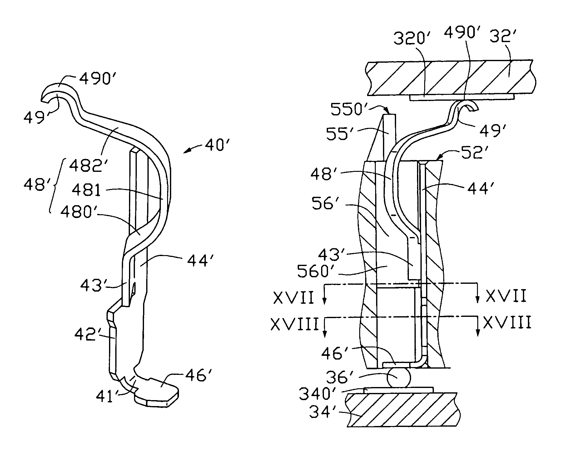
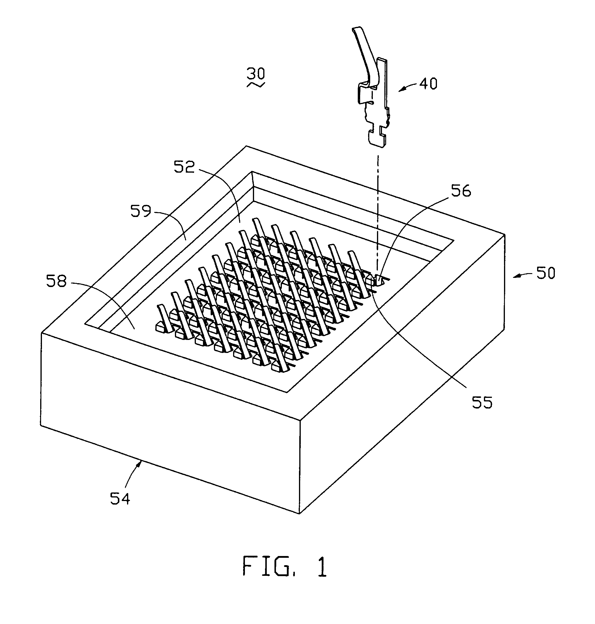
[0041]Referring to FIG. 1, an electrical connector 30 has a plurality of conductive LGA contacts 40 according to a first preferred embodiment of the present invention, and a simplified dielectric housing 50 shaped to cater for the contacts 40. The electrical connector 30 is mainly used to electrically connect two electrical components, e.g. an IC package 32 and a PCB 34 (referring to FIG. 7, hereinafter detailed), but not limited thereto.

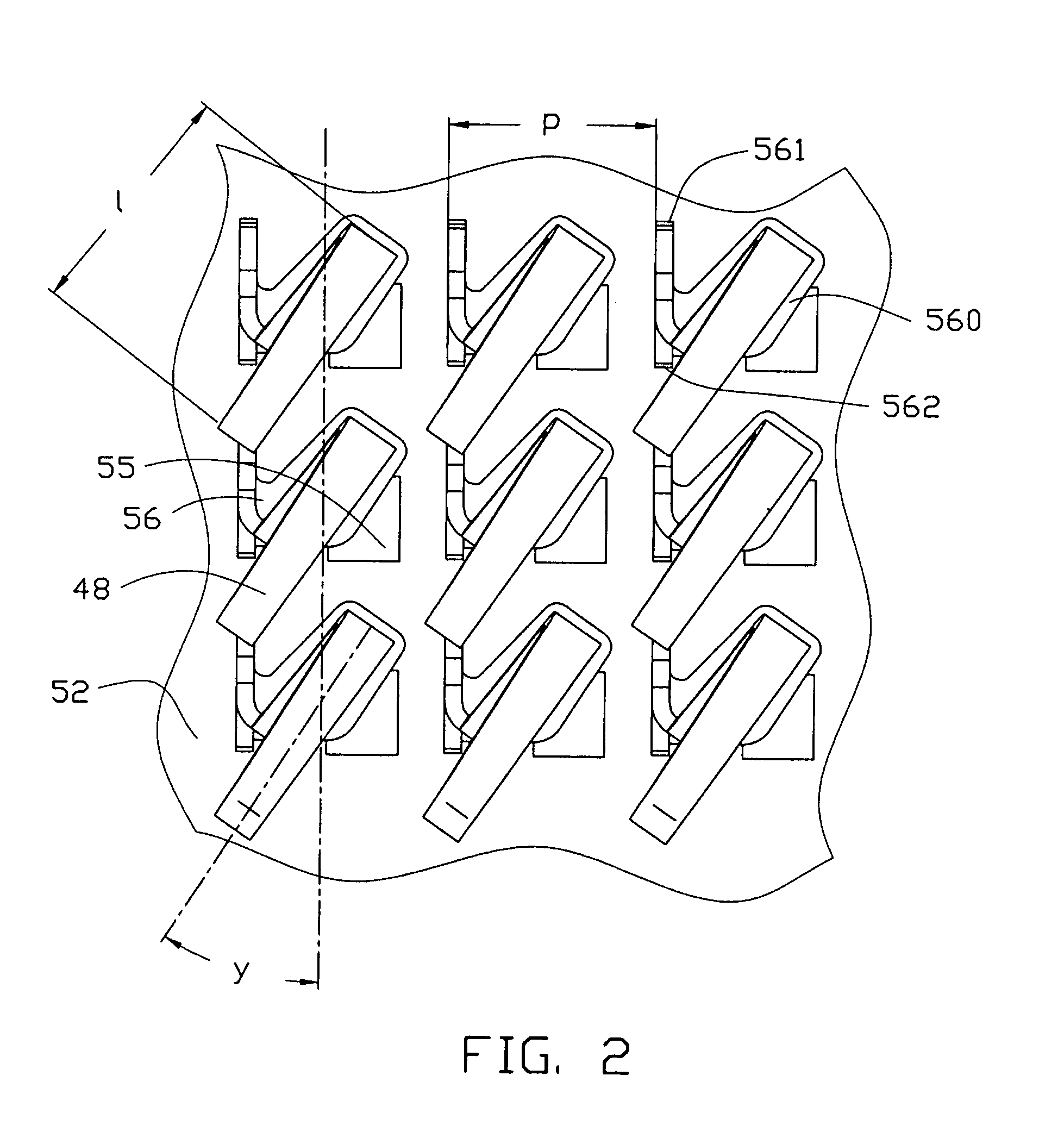
[0042]The housing 50 is formed from dielectric material and defines a horizontal top surface 52 and a bottom surface 54 opposite and parallel to the top surface 52. A plurality of cavities56 is defined in the housing 50 between the top surface 52 and the bottom surface 54 and arranged in rows and columns, for receiving corresponding contacts 40 therein. Further, an opening 58 is defined in a center of a top of the housing 50 above the cavities 56 and in comm...


PUM


Abstract

An LGA contact (40, 40′) for electrically connecting an IC package (32, 32′) and a PCB (34, 34′) includes a vertical basic part (42 and 44, 42′ and 44′), a vertical section (43, 43′) bendedly outwardly extending from a lateral side of the vertical basic part, an arm (48, 48′) extending upwardly from a top of said vertical section and a contacting portion (49, 49′) extending from an distal end of the arm. The arm has a rearwardly extending portion (482, 482′) and a forwardly extending portion (480, 480′). Further, two projections of the vertical section and the vertical basic part on a horizontal surface form an acute angle therebetween, thereby the arm can be devised to be relatively long to get good spring characteristics and many of this kind of contacts can be arranged in a relative less pitch as being assembled a housing (50, 50′).

Description

BACKGROUND OF THE INVENTION[0001]1. Field of the Invention[0002]The present invention relates to electrical connectors and, more specifically to a contact planted on a dielectric housing of an electrical connector adapted to electrically mate an integral circuit (IC) package such as a central processing unit (CPU), with an electrical substrate such as a printed circuit board (PCB), wherein the contact is configured to have a long spring arm to improve spring characteristics thereof.[0003]2. Description of the Prior Art[0004]With the development of the connector industry toward the miniaturized, high-density and more reliable trends, generally, terminals or contacts secured on connectors, especially certain connectors used for electrically interconnecting an IC package, especially an land grid array (LGA) package with high-density leads or pads thereon with a PCB, are configured to be tiny and arranged in a high-density manner, e.g. a rectangular array, to catch up with the trends. T...

Claims


Application Information

Patent Timeline
Patent Type & Authority Patents(United States)
IPC IPC(8): H01R4/48H01R4/02H01R12/04H01R12/55H01R12/57H01R13/05H01R13/24
CPCH01R13/2442H01R4/024H01R13/05H01R12/57
Inventor HOWELL, DAVID G.
Owner HON HAI PRECISION IND CO LTD
Why Eureka
Try Eureka