Motor vehicle drivetrain having at least two CNT's and flywheels

a technology of motor vehicles and drivetrains, applied in the direction of gearing, mechanical control devices, instruments, etc., can solve the problems of reducing the overall efficiency, cost, weight of batteries and electric motors, overall thermal efficiency, etc., and achieve the effect of a simple and far more efficient motor vehicle drivetrain

Inactive Publication Date: 2005-10-18
BRASS DWIGHT STANFORD
View PDF16 Cites 12 Cited by
  • Summary
  • Abstract
  • Description
  • Claims
  • Application Information

AI Technical Summary

Benefits of technology

[0008]The object of this invention is to provide a...

Problems solved by technology

Each component reduces the overall efficiency.
Specific problems with gas-electric hybrids include cost, weight of batteries and electric motor, and overall thermal eff...

Method used


Image

  • Motor vehicle drivetrain having at least two CNT's and flywheels
  • Motor vehicle drivetrain having at least two CNT's and flywheels
  • Motor vehicle drivetrain having at least two CNT's and flywheels

Examples


Embodiment Construction

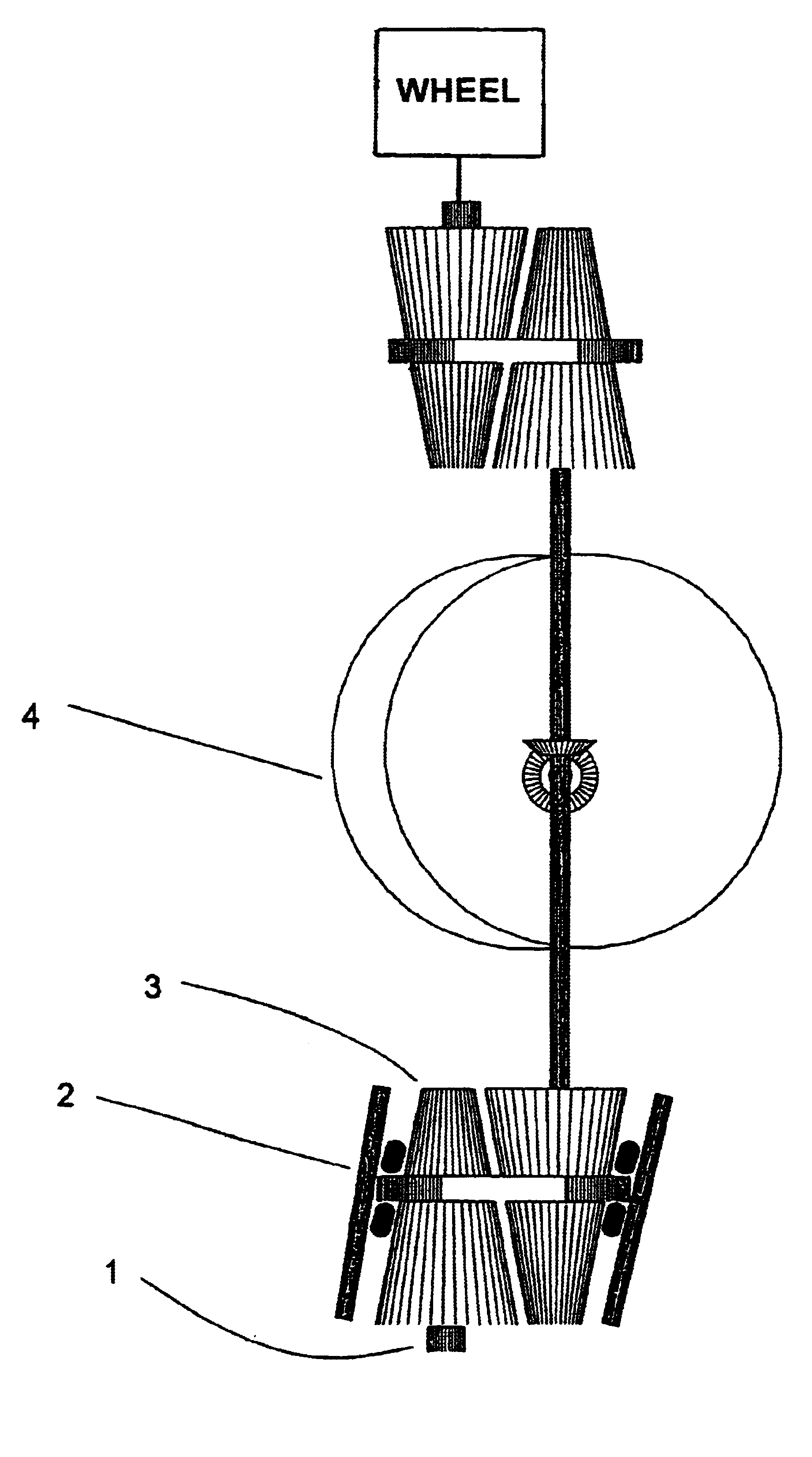
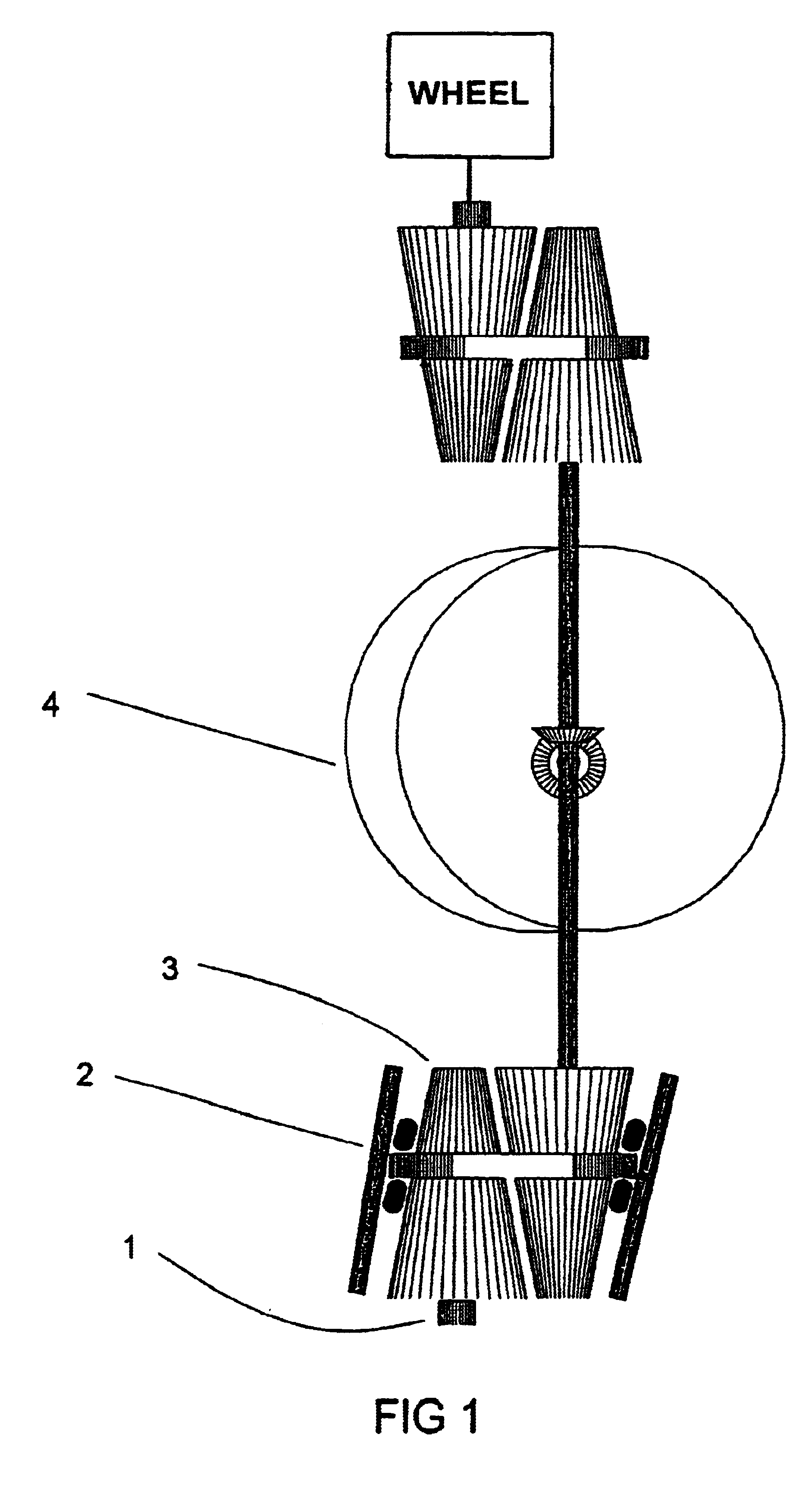
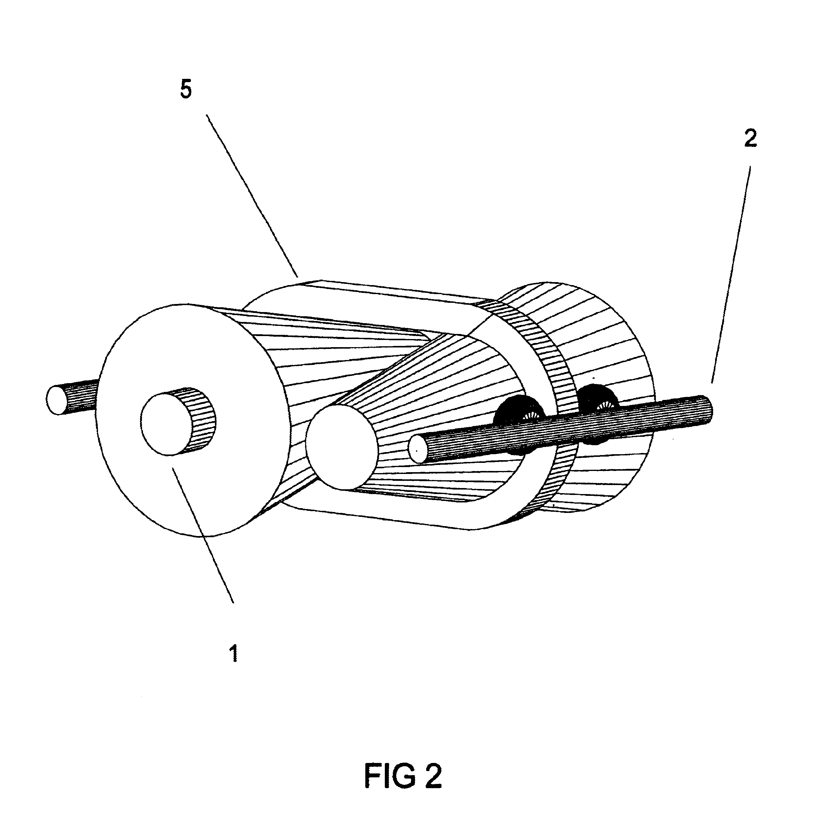
[0018]A continously variable ratio transmission 3 (CVRT), transfers power from the engine torque converter via the input shaft 1 (not part of this patent application) to the flywheel set 4, is controlled by an onboard programmable logic controller (PLC). This PLC receives inputs from the input shaft's RPM, the flywheel set's RPM, and torque on the input shaft I and adjusts the transmission by moving the shuttle control 2 which moves the drive belt. The program is set to a constant torque and a maximum flywheel RPM is specified. Initially, the flywheel set is accelerated at the maximum torque specified, until, and if, it reaches maximum RPM. The torque and RPM maximum are dependent on flywheel material and design, and the intended goal of the programmer (acceleration vs high mileage). Once the flywheel reaches maximum speed, the torque is reduced by changing the ratio of CVRT 3, allowing the flywheel to slow as demand for power is received from the second CVRT. At all times the engin...


PUM


Abstract

This design is for a motor vehicle drivetrain utilizing flywheel rotation to store energy during the vehicle trip, either storing energy when accellerated, or releasing energy when slowed depending on the vehicle power requirements. At the same time the engine is allowed to operate at a constant RPM and throttle setting, determined by the best thermal efficiency of the engine selected (the engine itself is not a part of this patent application). The continously variable speeds of the vehicle are made possible by the design's transmissions using sintered metal construction, a cogged drive belt, and a pattern of surface protrusions meshing with the cogged drive belt. The flywheels are slightly offset to allow simple gear meshing, and are counter-rotating to cancel out flywheel precession and torque reaction when providing power to the drive wheels. This eliminates any adverse effect on the vehicle's behavior that might otherwise result such as causing the vehicle to spin on slippery surfaces.

Description

CROSS-REFERENCE TO RELATED APPLICATIONS[0001]This application follows Provisional Application No. 60 / 432,944, with filing date of Dec. 12, 2002 which is claimed for this application.BACKGROUND OF THE INVENTION[0002]Motor vehicle drivetrain efficiency is constantly being improved, with a major advancement involving hybrid technology using a gasoline engine with a battery storage system and an electric motor. Current designs have included a regenerative braking feature that uses electric motor braking in order to recharge the storage batteries. Improved fuel economy is obtained by use of a relative small gasoline engine operating alternately with the electric motor. When the driver indicates demand for more power, both the gas and electric are utilized. The thermal efficiency of this design is the cumulative result of the gasoline engine, engine driven generator, storage battery, and electric motor. Each component reduces the overall efficiency. The regenerative braking recaptures som...

Claims


Application Information

Patent Timeline
IPC IPC(8): F16H15/04F16H15/42F16H9/08F16H9/02
CPCF16H15/42F16H9/08Y10T74/1933
Inventor BRASS, DWIGHT STANFORD
Owner BRASS DWIGHT STANFORD
Why Eureka
Try Eureka