Method and system for compressing and dehydrating wet natural gas produced from low-pressure wells

a technology low-pressure wells, which is applied in the direction of liquid degasification, domestic cooling devices, separation processes, etc., can solve the problems of both compression and dehydration of wet natural gas, and achieve the effect of greater efficiencies in low-pressure natural gas production

Inactive Publication Date: 2005-10-18
RDC RES
View PDF32 Cites 21 Cited by
  • Summary
  • Abstract
  • Description
  • Claims
  • Application Information

AI Technical Summary

Benefits of technology

[0021]It is an object of the present invention to create greater effic

Problems solved by technology

Operation of the rotary screw compressor causes both

Method used


Image

  • Method and system for compressing and dehydrating wet natural gas produced from low-pressure wells
  • Method and system for compressing and dehydrating wet natural gas produced from low-pressure wells
  • Method and system for compressing and dehydrating wet natural gas produced from low-pressure wells

Examples


Embodiment Construction

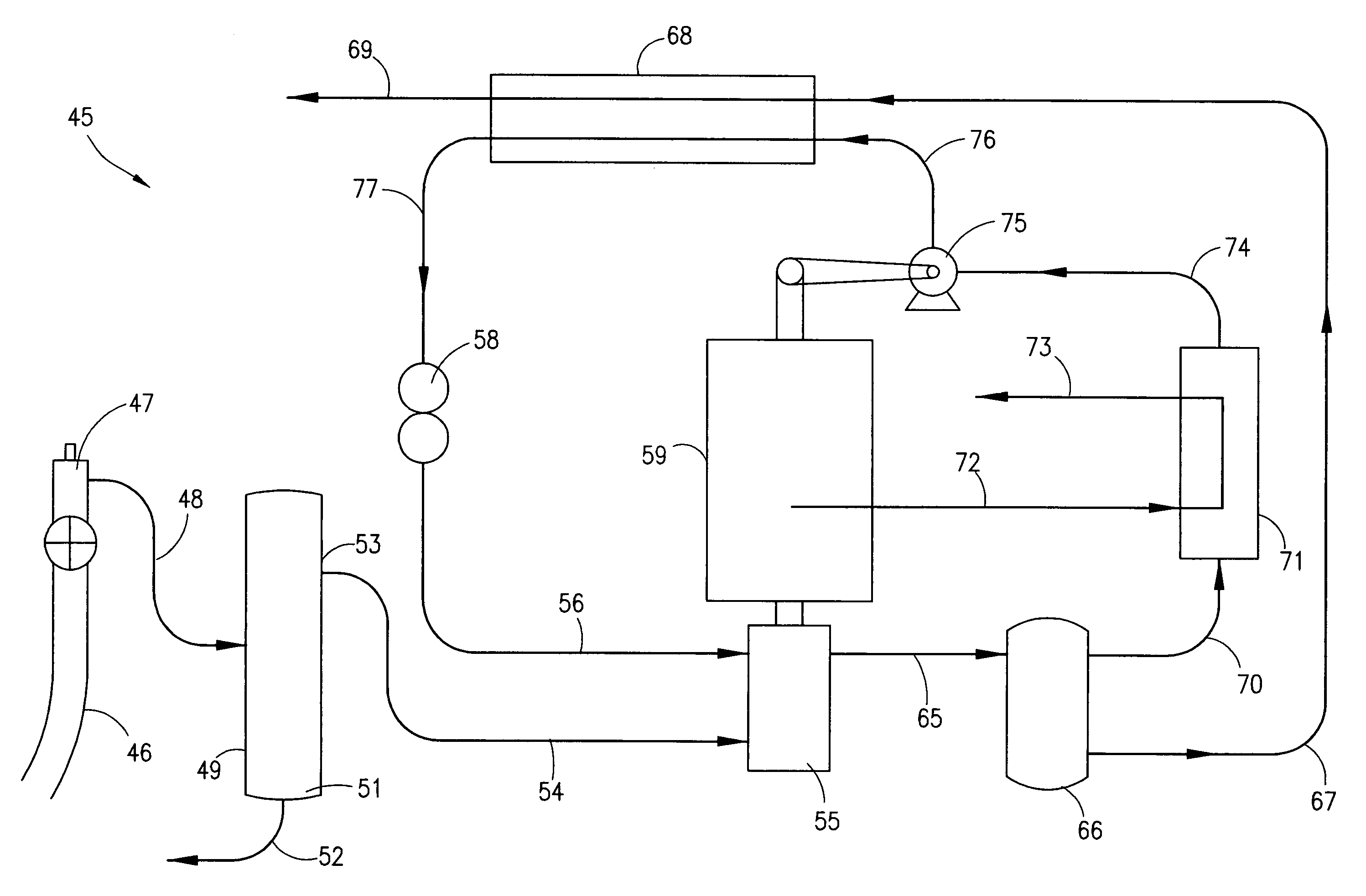
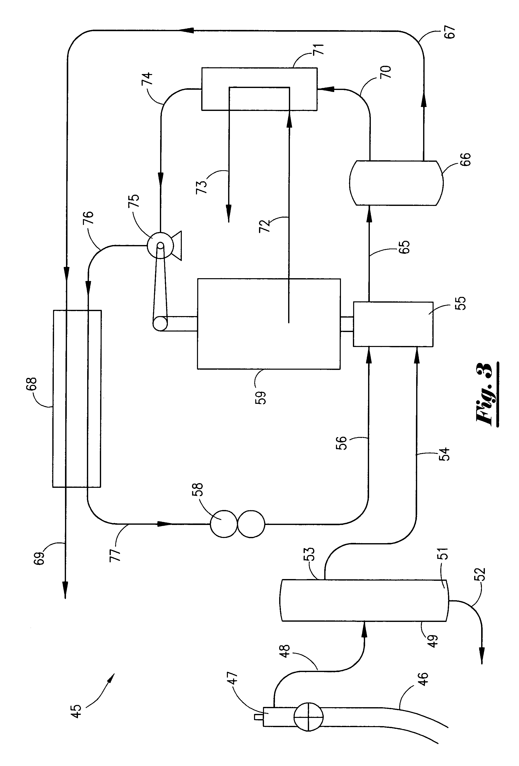
[0068]With reference to the figures where like elements have been given like numerical designation to facilitate an understanding of the present invention, and particularly with reference to the embodiment of the compression and dehydration system 45 of the present invention illustrated in FIGS. 3–10, a hydrocarbon production produced from low-pressure well 46 is fed from wellhead 47 through line 48 to inlet scrubber 49. Inlet scrubber 49 may be a conventional scrubber apparatus for removing free liquid and solid contaminants from a natural gas stream. The hydrocarbon production is passed up through inlet scrubber 49 which separates wet natural gas 50 from any free liquid and / or solid contaminants in the hydrocarbon production. The liquid and / or solid contaminants settle at the bottom portion 51 of inlet scrubber 49 and are discharged therefrom via line 52 for disposal.

[0069]Wet natural gas 50 passes from upper portion 53 of inlet scrubber 49 through line 54 to rotary screw compress...


PUM

PropertyMeasurementUnit
Temperatureaaaaaaaaaa
Heataaaaaaaaaa

Abstract

Method and system for compressing and dehydrating wet natural gas produced from a low-pressure well using a rotary screw compressor. A dehydrating agent is combined with wet natural gas within a rotary screw compressor. Operation of the rotary screw compressor causes compression and dehydration of the wet natural gas to produce a compressed dry natural gas. Engine exhaust produced by the engine which powers the rotary screw compressor may be used to remove water absorbed by the dehydrating agent and thereby recover the dehydrating agent for re-circulation in the system.

Description

FIELD OF THE INVENTION[0001]The present invention relates to methods and systems for compressing and dehydrating wet natural gas produced from low-pressure wells, and more particularly, to methods and systems for compressing and dehydrating wet natural gas produced from low-pressure wells using rotary screw compression technology.BACKGROUND OF THE INVENTION[0002]Declining pressures in natural gas fields has resulted in the use of rotary screw compressors as wellhead boosters. Rotary screw compressors are designed for low pressure applications with inlet pressures up to 100 psig and discharge pressures up to 350 psig.[0003]Rotary screw compressors are described in U.S. Pat. Nos. 6,506,039, 6,217,304, and 6,216,474, the disclosures of which are incorporated herein by reference. The main components include one set of male and female helically grooved rotors, a set of axial and radial bearings, and a slide valve, which are all encased in a common housing. As the rotors begin to un-mesh,...

Claims


Application Information

Patent Timeline
IPC IPC(8): B01D53/26B01D19/00B01D53/14C10L3/10F25D9/00
CPCB01D53/263C10L3/10Y10S60/902
Inventor CHENEY, RICHARD P.SALZMAN, BRAD
Owner RDC RES
Why Eureka
Try Eureka