Prepackaged mounting assembly

a mounting assembly and pre-packaged technology, applied in the direction of bolts, coupling device connections, machines/engines, etc., can solve the problems of installation of the surrounding ceiling area, the installation of the bracket and the mounting assembly, and the installation of the installation of the mounting assembly

Inactive Publication Date: 2005-10-18
GRETZ THOMAS J +1
View PDF9 Cites 17 Cited by
  • Summary
  • Abstract
  • Description
  • Claims
  • Application Information

AI Technical Summary

Benefits of technology

[0008]Although the mounting assembly of U.S. application Ser. No. 10/790,973 provided a means of aligning the bracket with the mounting assembly and the beam, as a result of its oversized junction box, it was especially useful for mounting an electrical device to an unfinished ceiling, in which the beams are bare and exposed or in which the sheet rock

Problems solved by technology

Although the alternate embodiment disclosed in U.S. Pat. No. 6,646,201 provided enabled the L-shaped mounting assembly to accommodate an oversize manufacturer's bracket, it was difficult to align the bracket with the mounting assembly and the beam to which it was attached.
If the mounting assembly

Method used


Image

  • Prepackaged mounting assembly
  • Prepackaged mounting assembly
  • Prepackaged mounting assembly

Examples


Embodiment Construction

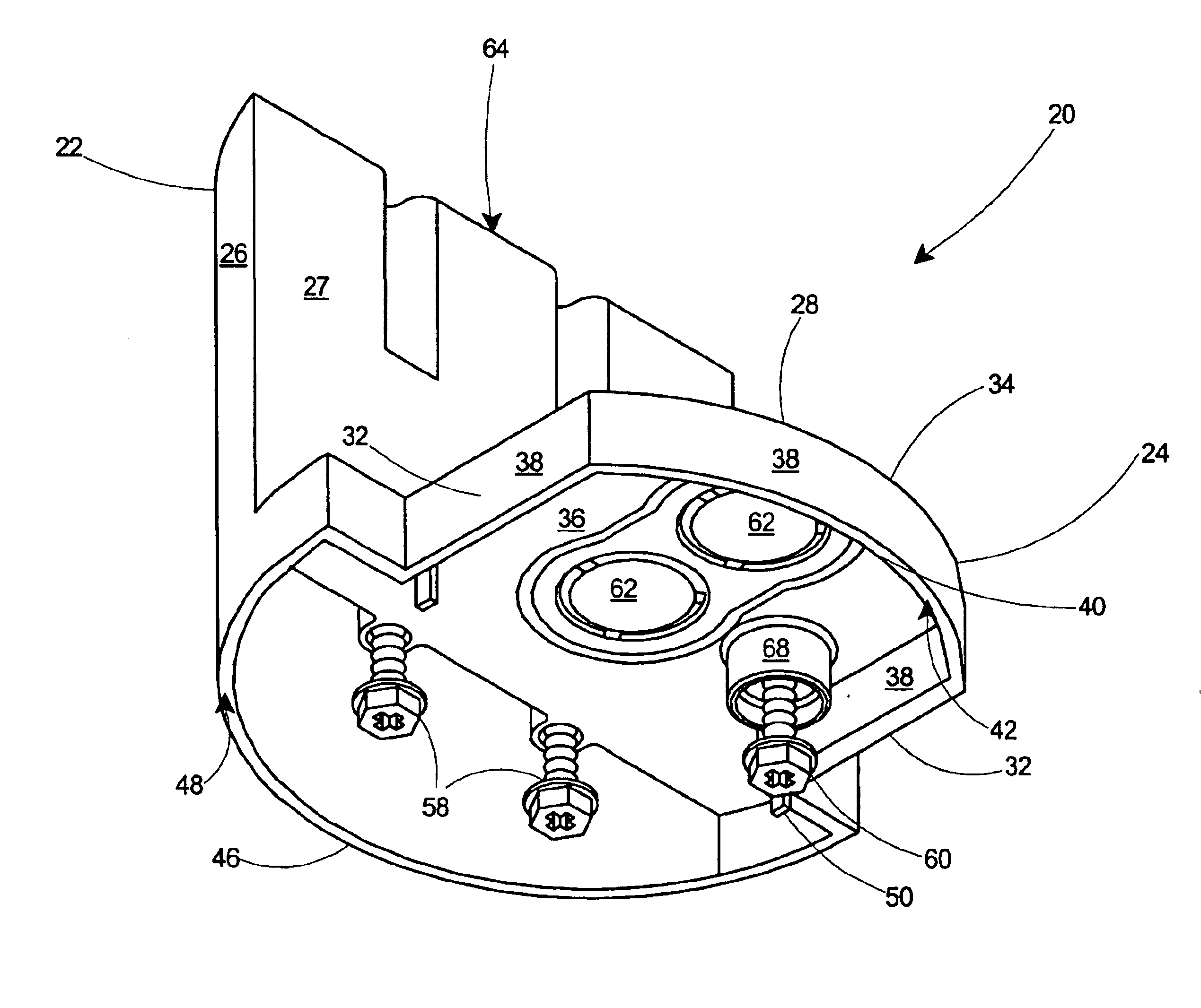
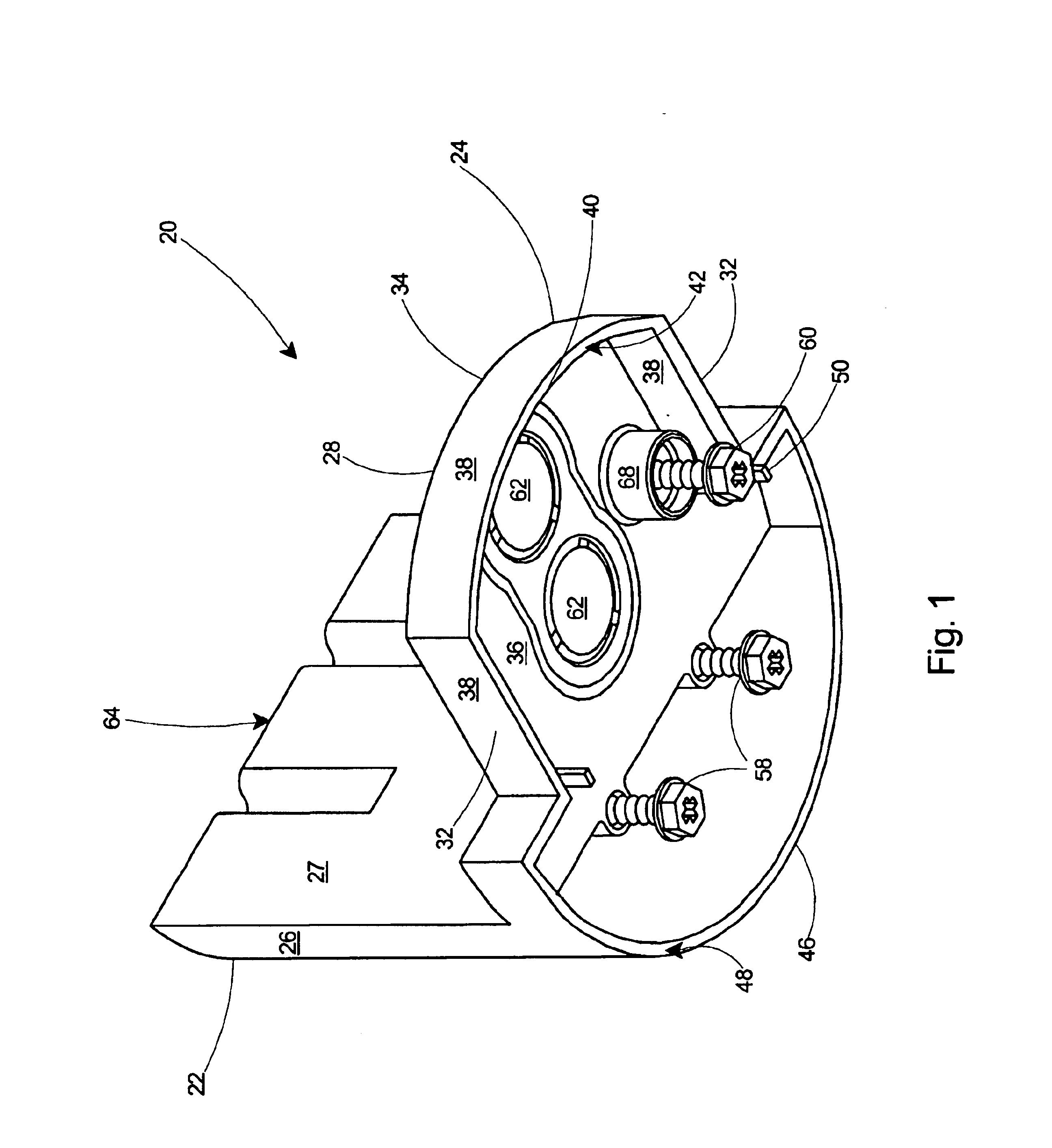
[0024]The present invention is a prepackaged mounting assembly for mounting a suspended electrical fixture from an overhead beam and is especially adapted for a retrofit application, in which the ceiling is finished.

[0025]With reference to FIG. 1, a preferred embodiment is shown of the prepackaged mounting assembly 20 which includes a first 22 and a second 24 junction box integrally formed in one piece. The first junction box 22 has deep side walls including an arcuate side wall 26 and a flat side wall 27. The second junction box 24 includes a top 28 that is integral with and extends orthogonally from the flat side wall 27 of the first junction box 22.

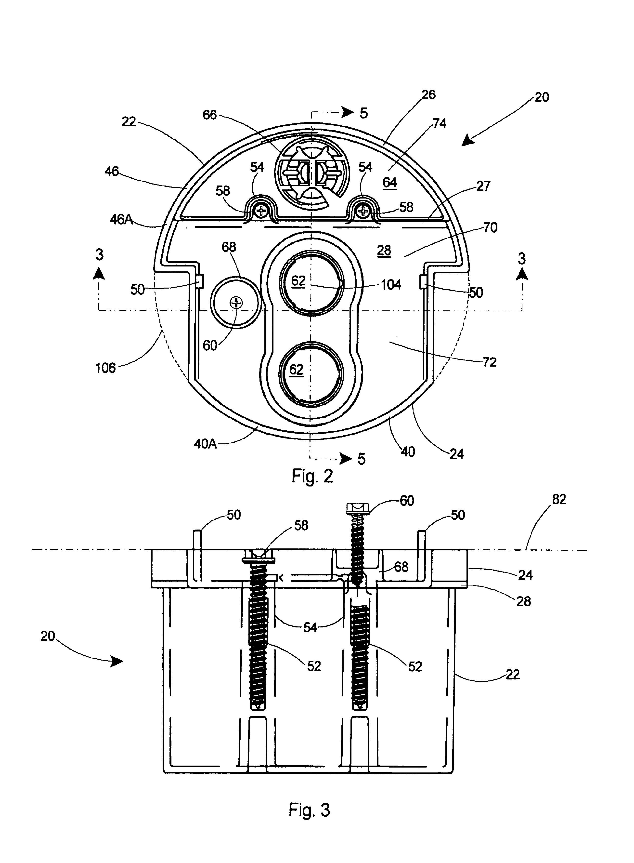
[0026]Referring to FIGS. 1 and 2, the top 28 of the second junction box 24 includes two opposing sides 32, a distal end 34, and a lower surface 36. Integral side walls 38 extend downward from the lower surface 36 of the top 28 along the distal end 34 and along the opposing sides 32 of the second junction box 24. The side walls 38 of th...


PUM


Abstract

A prepackaged mounting assembly for securing a device, such as a ceiling fan, light fixture, or similar device to an overhead beam. The mounting assembly includes an L-shaped mounting box that includes a first and a second junction box. Each junction box includes an integral arcuate flange portion that cooperate to accept a separately supplied bracket thereon. The bracket includes slots therein and the integral flange portion includes downward extending alignment posts to enable easy centering of the bracket under the mounting box and the overhead beam. All hardware required to complete installation of the device is temporarily secured to the L-shaped box for shipment and storage, including an initial fastener and load bearing fasteners. The L-shaped mounting assembly is especially useful for mounting an electrical device to an existing ceiling.

Description

[0001]This application is a Continuation-In-Part of U.S. patent application Ser. No. 10 / 790,973 entitled “Prepackaged Mounting Assembly”, filed Mar. 3, 2004 now U.S. Pat. No. 6,794,573, which is a Continuation-In-Part of U.S. patent application Ser. No. 10 / 723,122 entitled “Fan Rated Junction Box Assembly”, filed Nov. 26, 2003 now U.S. Pat. No. 6,777,615, which is a Continuation-In-Part of U.S. patent application Ser. No. 10 / 464,334 entitled Prepackaged Mounting Assembly and Bracket Combination, filed Jun. 18, 2003 now U.S. Pat. No. 6,734,356, which is a Continuation-In-Part of 10 / 361,292 entitled “Prepackaged Mounting Assembly with Holstered Screws”, filed Feb. 10, 2003 now U.S. Pat. No. 6,632,998, which is a Continuation-In-Part of U.S. patent application Ser. No. 10 / 287,088 entitled “Prepackaged Mounting Assembly”, filed Nov. 4, 2002 now U.S. Pat. No. 6,646,201, which is a Continuation-In-Part of U.S. patent application Ser. No. 10 / 012,584 entitled “Prepackaged Mounting Assembly”...

Claims


Application Information

Patent Timeline
IPC IPC(8): H01H9/02E04B9/00F04D25/08F04D29/60F16B41/00H02G3/12H02G3/20
CPCE04B9/006F04D25/088F04D29/601F16B41/002H02G3/126H02G3/20
Inventor GRETZ, THOMAS J.OFCHARSKY, JOHN
Owner GRETZ THOMAS J
Why Eureka
Try Eureka