Light emitting diode

a technology of light-emitting diodes and diodes, which is applied in the direction of basic electric elements, electrical equipment, and semiconductor devices, can solve the problems of shortened service life and inability to endure high, and achieve excellent heat resistance, enhanced life span and reliability of leds, and excellent heat resistan

Active Publication Date: 2005-10-18
EPISTAR CORP
View PDF3 Cites 29 Cited by
  • Summary
  • Abstract
  • Description
  • Claims
  • Application Information

AI Technical Summary

Benefits of technology

[0003]Thus, a primary objective of the present invention is to provide a light emitting diode (LED) comprising a reflector cup accommodating LED dices that are properly wired and a glass lens containing fluorescent powders located at a position corresponding to the LED dices, which glass lens offers excellent heat resistance and thus enhanced life span and reliability of the LED.
[0004]To achieve the above objective, in accordance with the present invention, a light emitting diode (LED) is provided, comprising a base, a reflector cup, a plurality of LED dices, a plastic layer, and a glass lens. External terminals are mounted in the base. The reflector cup is received and fixed in the base and forms a recess in which the dices are received and fixed. The dices are connected by conductors to the external terminals. The plastic layer is filled in the base to seal the reflector cup, the dices, the conductors, and portions of the external terminals. A bottom of the reflector cup is exposed outside the plastic layer and the external terminals extend beyond the plastic layer. The lens is made of glass containing fluorescent powders and is positioned on the plastic layer so as to correspond in position to the LED dices. This offers an excellent heat resistance and thus enhances the life span and reliability of the LED.

Problems solved by technology

Although the conventional structure LED realizes the emission of color light, the material used to package the LED, such as the transparent plastics 7 and the fluorescent layer 8, is not capable to endure high temperature and the service life of the LED is shortened due to the poor heat resistance thereof.

Method used


Image

  • Light emitting diode
  • Light emitting diode
  • Light emitting diode

Examples


Embodiment Construction

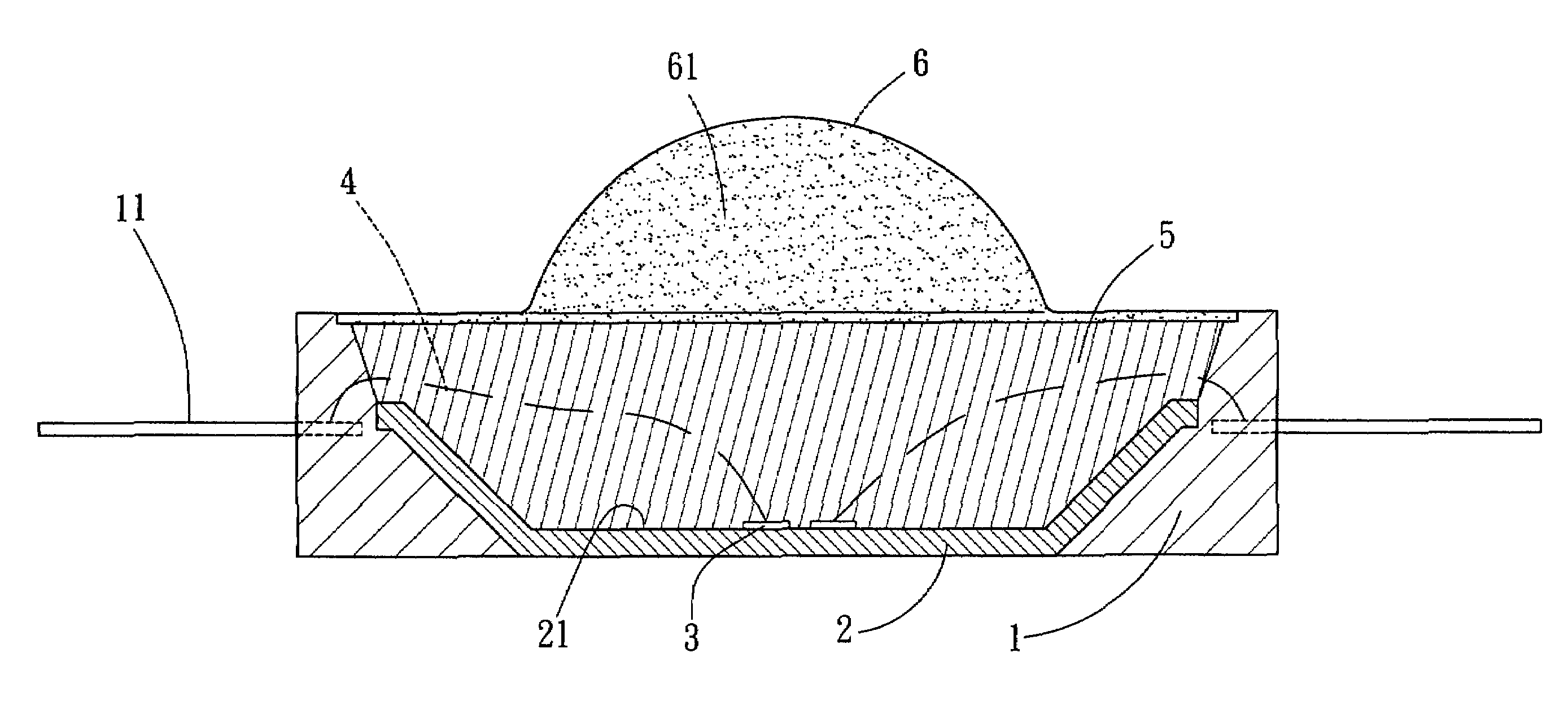
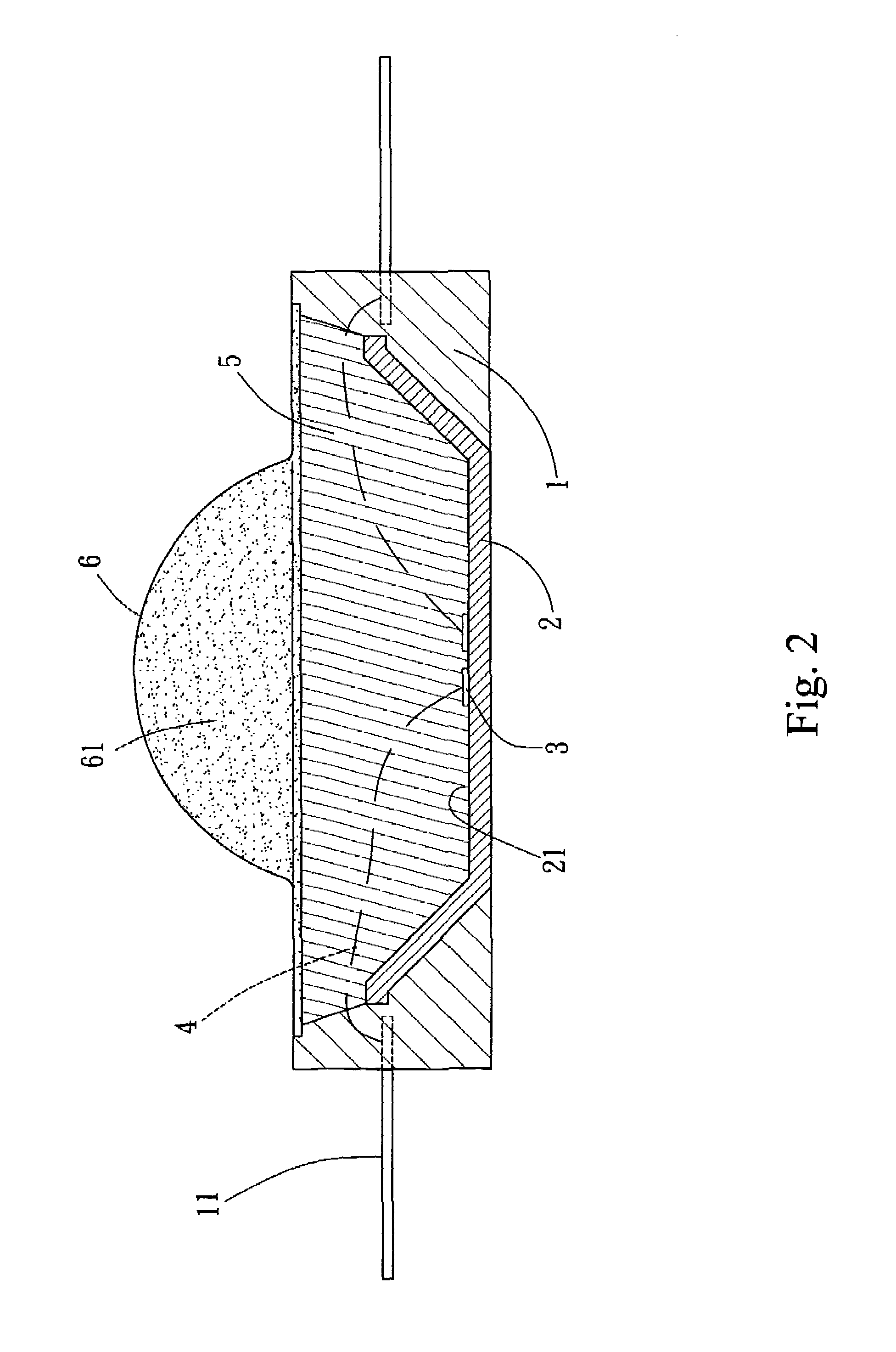
[0008]With reference to the drawings and in particular to FIG. 2, a light emitting diode (LED) constructed in accordance with the present invention comprises a base 1 from which two terminals 11 extend in opposite directions for connection with an external power source (not shown).

[0009]A reflector cup 2, which is made of for example ceramics, plastics, and metals, is received and fixed in the base 1. The reflector cup 2 defines a recess 21 in which a plurality of LED dices 3 is received and fixed. Conductors 4 connect the dices 3 to the terminals 11 of the base 1.

[0010]A plastic layer 5 is filled in the base 1 to seal the reflector cup 2, the dices 3, the conductors 4, and portions of the terminals 11. The plastic layer 5 is formed in such a way to allow a bottom of the reflector cup 2 exposed outside the plastics 5 and the terminals 11 extending beyond the plastics 5.

[0011]A lens 6 made of glass is positioned on the plastic layer 5 at a location corresponding to the dices 3 and cl...


PUM


Abstract

A light emitting diode (LED) includes a base, a reflector cup, a plurality of LED dices, a plastic layer, and a glass lens. External terminals are mounted in the base. The reflector cup is received and fixed in the base and forms a recess in which the dices are received and fixed. The dices are connected by conductors to the external terminals. The plastic layer is filled in the base to seal the reflector cup, the dices, the conductors, and portions of the external terminals. A bottom of the reflector cup is exposed outside the plastic layer and the external terminals extend beyond the plastic layer. The lens is made of glass containing fluorescent powders and is positioned on the plastic layer at a position corresponding to the dices. The glass lens that has a high melting point offers an excellent heat resistance and thus enhances the life span and reliability of the LED.

Description

FIELD OF THE INVENTION[0001]The present invention generally relates to a light emitting diode (LED), and in particular to a LED featuring good heat resistance by providing a glass lens containing fluorescent powders therein at a location corresponding to an LED dice to replace a conventional lens made of plastics, such as epoxy resin, PC, PMMA, PEI, PC / PMMA, and COC, which has poor heat resistance, whereby the overall service life and operation reliability of an LED based lighting device can be extended and a lighting device with intense light can be obtained with such a with LED structure.BACKGROUND OF THE INVENTION[0002]A conventional light emitting diode (LED), as shown in FIG. 1 of the attached drawings, comprises two lead frames 71, 72 packaged in transparent plastics 7. One of the lead frames, for example lead frame 71, has a top end defining a recess 711 in which an LED dice 73 is accommodated. A gold wire 74 connects the dice 73 to the other lead frame 72. A fluorescent laye...

Claims


Application Information

Patent Timeline
Patent Type & Authority Patents(United States)
IPC IPC(8): H01L27/15H01L31/12H01L33/48H01L33/50H01L33/58
CPCH01L33/505H01L33/58H01L33/486H01L2224/48091H01L2224/48247H01L2224/73265H01L2924/00014H01L2224/8592H01L2224/45144H01L2924/00H01L2924/181H01L2924/00012
Inventor CHIN, YUAN-CHENG
Owner EPISTAR CORP
Why Eureka
Try Eureka