Al technical title is built by PatSnap Al team. It summarizes the technical point description of the patent document.
a technology of debris sensor and cleaning apparatus, which is applied in the direction of carpet cleaners, distance measurement, instruments, etc., can solve the problems of degrading the performance of optical sensors, and achieve the effect of cleaning the debris field most effectively
Inactive Publication Date: 2005-10-18
IROBOT CORP
View PDF52 Cites 267 Cited by
Summary
Abstract
Description
Claims
Application Information
AI Technical Summary
This helps you quickly interpret patents by identifying the three key elements:
Problems solved by technology
Method used
Benefits of technology
[0023]The debris sensor of the invention can also be incorporated into a non-autonomous cleaning apparatus. This aspect of the invention can include a piezoelectric sensor located proximate to a cleaning pathway and responsive to a debris strike to generate a debris signal indicative of such strike; and a processor responsive to the debris signal to change an operative mode of the cleaning apparatus. The change in operative mode could include illuminating a user-perceptible indicator light, changing a power setting (e.g., higher power setting when more debris is encountered), or slowing or reducing a movement speed of the apparatus.
[0025]Another aspect of the invention takes advantage of the motion of an autonomous cleaning device across a floor or other surface, processing the debris signal in conjunction with knowledge of the cleaning device's movement to calculate a debris gradient. The debris gradient is representative of changes in debris strikes count as the autonomous cleaning apparatus moves along a surface. By examining the sign of the gradient (positive or negative, associated with increasing or decreasing debris), an autonomous cleaning device controller can continuously adjust the path or pattern of movement of the device to clean a debris field most effectively.
Problems solved by technology
During usage of the vacuum cleaner, therefore, dust particles tend to adhere to the exposed surfaces of the light transmitter and the light receiver, through which light is emitted and detected, eventually degrading the performance of the optical sensor.
In addition, debris sensors typical of the prior art are sensitive to a level of built-up debris in a reservoir or cleaning pathway, but not particularly sensitive to instantaneous debris strikes or encounters.
Method used
Image
Click on the blue label to locate the original text in one second.
Reading with bidirectional positioning of images and text.
Examples
Embodiment Construction
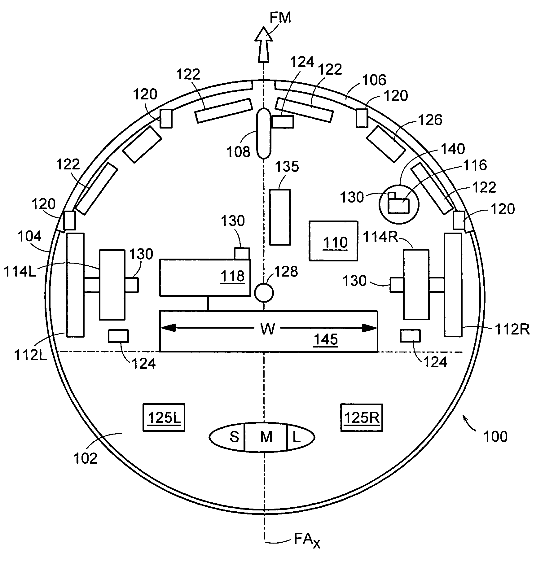
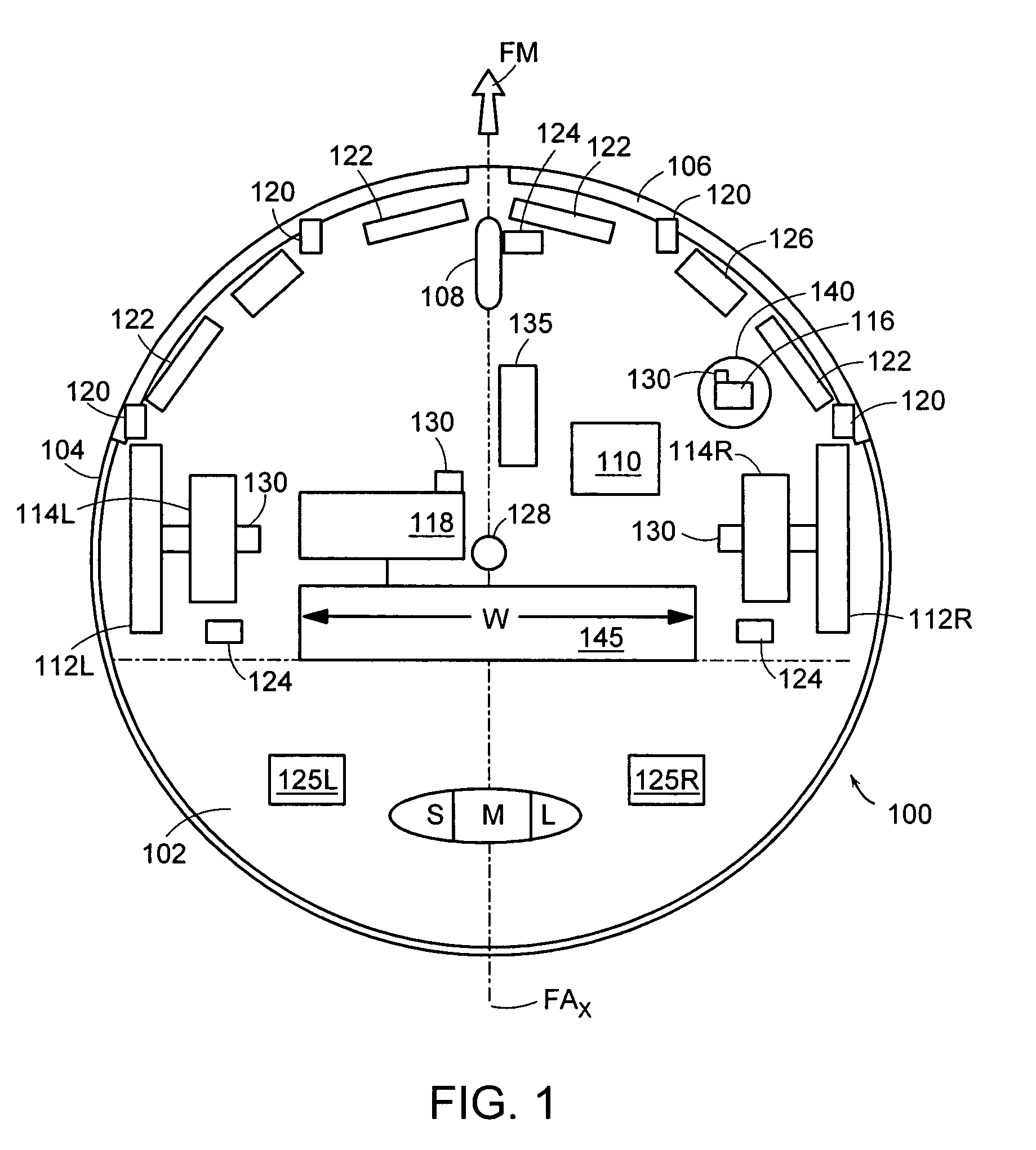
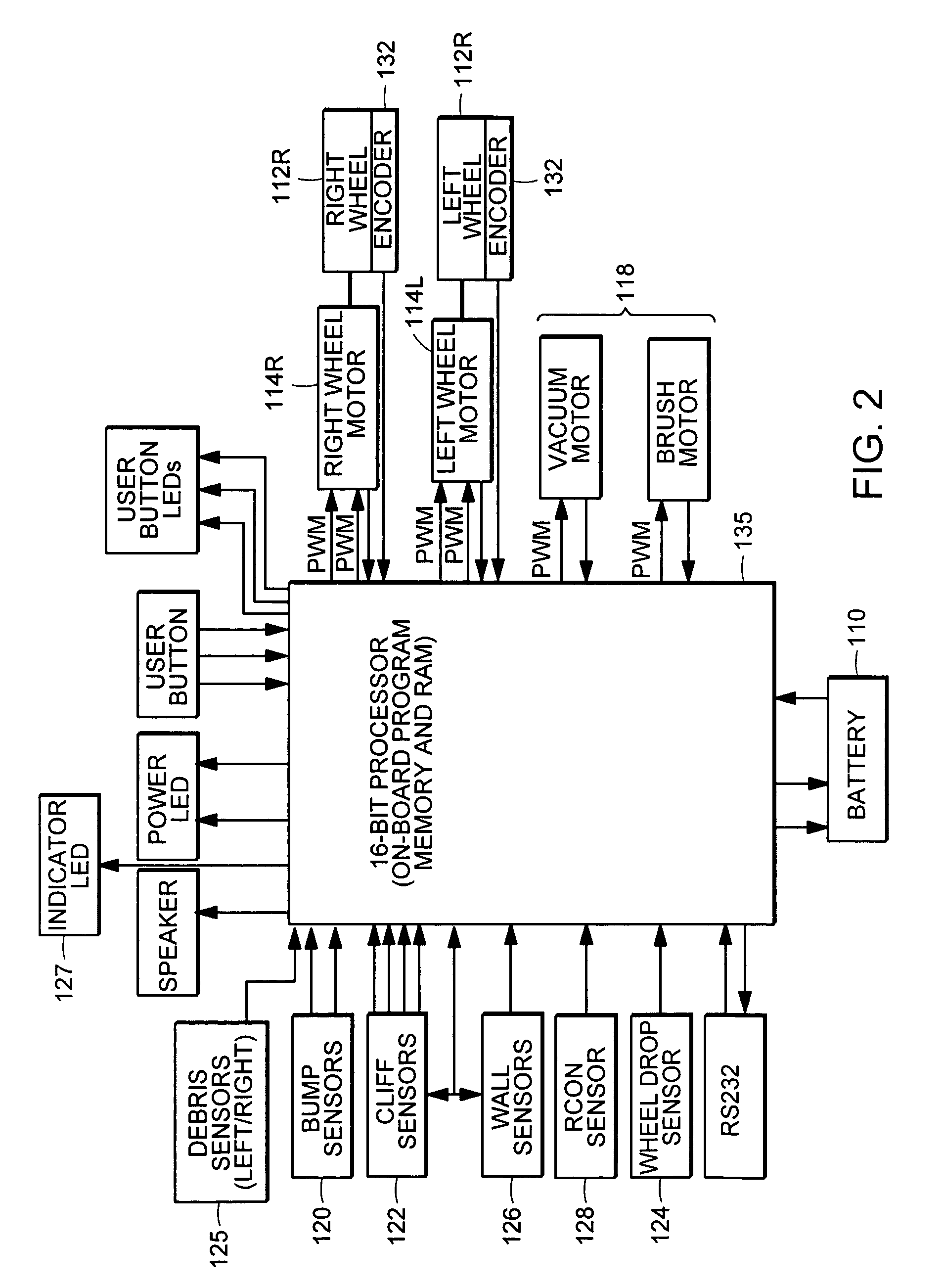
[0036]While the debris sensor of the present invention can be incorporated into a wide range of autonomous cleaning devices (and indeed, into non-autonomous cleaning devices as shown by way of example in FIG. 7), it will first be described in the context of an exemplary autonomous cleaning device shown in FIGS. 1–3. Further details of the structure, function and behavioral modes of such an autonomous cleaning device are set forth in the patent applications cited above in the Cross-Reference section, each of which is incorporated herein by reference. Accordingly, the following detailed description is organized into the following sections:[0037]I. Exemplary Autonomous Cleaning Device[0038]II. Behavioral Modes of an Autonomous Cleaning Device[0039]III. Debris Sensor Structure[0040]IV. Signal Processing[0041]V. Conclusions
[0042]I. Autonomous Cleaning Device
[0043]Referring now to the drawings wherein like reference numerals identify corresponding or similar elements throughout the severa...
PUM
Abstract
A piezoelectric debris sensor and associated signal processor responsive to debris strikes enable an autonomous or non-autonomous cleaning device to detect the presence of debris and in response, to select a behavioral mode, operational condition or pattern of movement, such as spot coverage or the like. Multiple sensor channels (e.g., left and right) can be used to enable the detection or generation of differential left / right debris signals and thereby enable an autonomous device to steer in the direction of debris.
Description
CROSS-REFERENCE TO RELATED PATENT DOCUMENTS[0001]The present application for patent is related to the following commonly-owned U.S. patent applications or patents, incorporated by reference as if fully set forth herein:[0002]U.S. patent application Ser. No. 09 / 768,773 filed Jan. 24, 2001, now U.S. Pat. No. 6,594,844, entitled Robot Obstacle Detection System;[0003]U.S. Provisional Patent Application Ser. No. 60 / 345,764 filed Jan. 3, 2002, entitled Cleaning Mechanisms for Autonomous Robot;[0004]U.S. patent application Ser. No. 10 / 056,804, filed Jan. 24, 2002, entitled Method and System for Robot Localization and Confinement;[0005]U.S. patent application Ser. No. 10 / 167,851 filed Jun. 12, 2002, entitled Method and System for Multi-Mode Coverage for an Autonomous Robot;[0006]U.S. patent application Ser. No. 10 / 320,729 filed Dec. 16, 2002, entitled Autonomous Floor-Cleaning Robot;[0007]U.S. patent application Ser. No. 10 / 661,835 filed Sep. 12, 2003, entitled Navigational Control System f...
Claims
Application Information
Patent Timeline
Application Date:The date an application was filed.
Publication Date:The date a patent or application was officially published.
First Publication Date:The earliest publication date of a patent with the same application number.
Issue Date:Publication date of the patent grant document.
PCT Entry Date:The Entry date of PCT National Phase.
Estimated Expiry Date:The statutory expiry date of a patent right according to the Patent Law, and it is the longest term of protection that the patent right can achieve without the termination of the patent right due to other reasons(Term extension factor has been taken into account ).
Invalid Date:Actual expiry date is based on effective date or publication date of legal transaction data of invalid patent.