Fail-safe zero delay buffer with automatic internal reference

a buffer and automatic reference technology, applied in the direction of automatic control, pulse, etc., can solve the problems of circuit timing generation loss and clock interruption, and achieve the effect of reducing or eliminating multiplexers, reducing or eliminating complex decision making/control logic, and simplifying clock system design

Inactive Publication Date: 2005-10-18
MONTEREY RES LLC
View PDF33 Cites 56 Cited by
  • Summary
  • Abstract
  • Description
  • Claims
  • Application Information

AI Technical Summary

Benefits of technology

[0009]The objects, features and advantages of the present invention include providing a method and/or architecture for a zero delay buffer with an automatic reference clock that may (i) simplify the design of clock systems, (ii) reduce or eliminate complicated decision making/control logic, (iii) reduce or eliminate multiplexers, (iv) eliminate “off chip” backup reference oscillators, (v) provide a phase aligned (e.g., phase coherent)

Problems solved by technology

Conventional timing systems can result in problems, for example, when used in communications systems that derive timing from incoming data streams.
Loss of the data stream (due to storm, interference, etc.) can result in loss of circuit timing generation unless a backup timing source is available.
However, conventional technology has the following disad

Method used


Image

  • Fail-safe zero delay buffer with automatic internal reference
  • Fail-safe zero delay buffer with automatic internal reference
  • Fail-safe zero delay buffer with automatic internal reference

Examples


Embodiment Construction

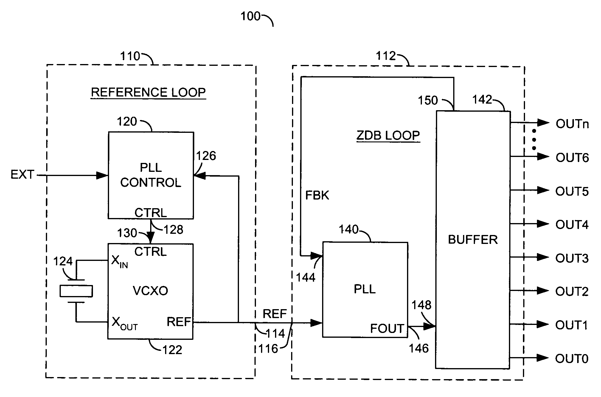
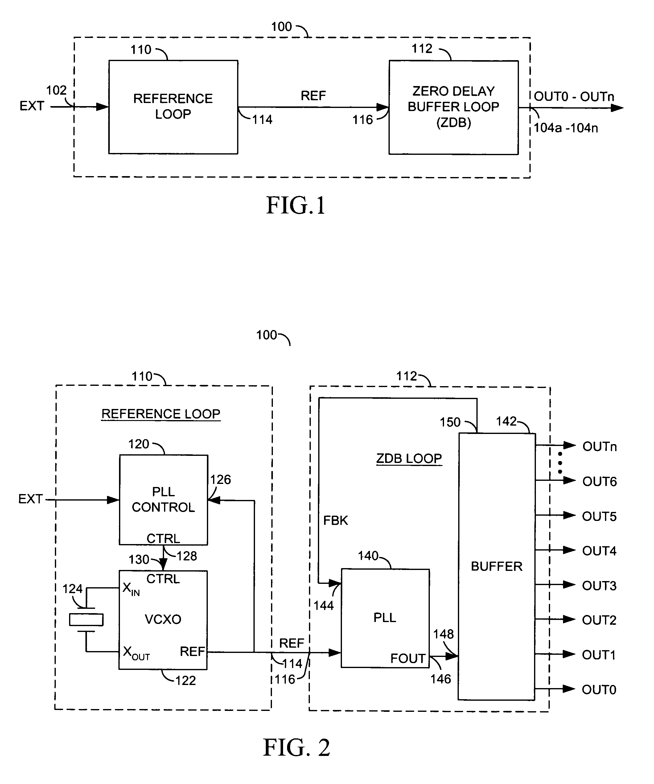
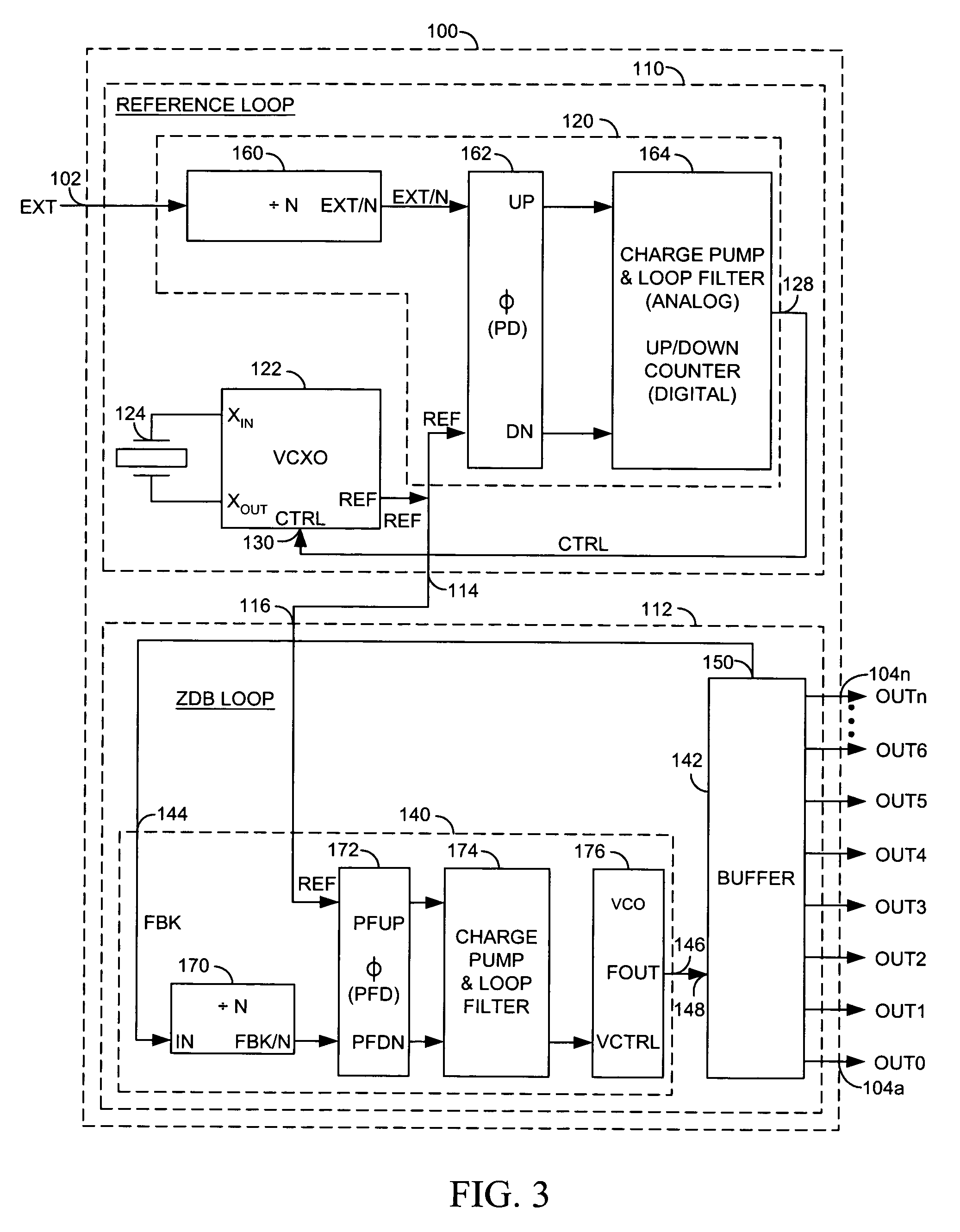
[0015]Referring to FIG. 1, a block diagram of a circuit 100 is shown in accordance with a preferred embodiment of the present invention. In one example, the circuit 100 may be implemented as a fail-safe zero delay buffer with an automatic reference circuit. The circuit 100 may have an input 102 that may receive a signal (e.g., EXT) and one or more outputs 104a–104n that may present one or more signals (e.g., OUT0–OUTn). The signal EXT may be a clock signal. In one example, the signal EXT may be an external reference signal. The signal EXT may be used as a primary reference for a zero delay buffer circuit. The signals OUT0–OUTn may be, in one example, output clock signals that may be in phase with each other and the signal EXT. The circuit 100 may be configured to buffer a signal with essentially no additional propagation delay in the signal path. The circuit 160 may be configured to provide a continuous clock even when the signal EXT is lost.

[0016]The circuit 100 may be configured t...


PUM


Abstract

An apparatus comprising a first circuit and a second circuit. The first circuit may comprise a control circuit and an oscillator. The control circuit may be configured to generate a control signal in response to a first reference signal and a second reference signal. The oscillator may be configured to generate the second reference signal in response to the control signal and a timing signal. The control signal is generally held when the first reference signal is lost. The second circuit may be configured to generate one or more output signals in response to the second reference signal and one of the one or more output signals. The one or more output signals may have a controlled delay with respect to the first reference signal.

Description

[0001]This is a continuation of U.S. Ser. No. 09 / 928,818, filed Aug. 13, 2001, now U.S. Pat. No. 6,768,362, issued Jul. 27, 2004.FIELD OF THE INVENTION[0002]The present invention relates to a method and / or architecture for implementing zero delay buffers generally and, more particularly, to a method and / or architecture for a zero delay buffer featuring an automatic reference loop which generates an internal reference clock that may be phase aligned to an externally supplied reference clock. In the event the externally supplied reference clock stops, the automatic reference loop will continue to supply an internal reference clock.BACKGROUND OF THE INVENTION[0003]A signal buffer that inserts essentially no additional propagation delay in the signal path is required for many applications. A phase locked loop (PLL) or delay locked loop (DLL) based zero delay buffer can address the requirement for essentially no additional propagation delay. A continuous clock, even in the event of loss ...

Claims


Application Information

Patent Timeline
IPC IPC(8): H03L7/087H03L7/08H03L7/089H03L7/099H03L7/16H03L7/23
CPCH03L7/087H03L7/089H03L7/099H03L7/23
Inventor MANN, ERIC N.WUNNER, JOHN J.
Owner MONTEREY RES LLC
Why Eureka
Try Eureka