Powerline data communication

a powerline and data technology, applied in the field of powerline data communication, can solve the problems of large complexity of the error correction scheme, the assumption of general non-integer values in the partial rate, and the inability to recover data from disturbed subchannels

Inactive Publication Date: 2005-10-18
POLYTRAX INFORMATION TECH
View PDF8 Cites 35 Cited by
  • Summary
  • Abstract
  • Description
  • Claims
  • Application Information

AI Technical Summary

Benefits of technology

[0014]It is an object of the invention to provide a method and an apparatus for data communication over a powerline network which are relatively simple and use a predetermined transmission channel efficiently.
[0032]Distributing the transmitted data stream to the subchannels and using methods for error correction in the transmitted data can be simplified if the transmission error rate is the same for each subchannel.

Problems solved by technology

However, the necessary error correcting scheme by means of channel coding to recover data from disturbed subchannels is relatively complicated.
To maximise the transmission rate, the partial rates R(i)=Δf·log2(1+SNR(i)) are chosen so as to be equal to the capacities of the subchannels, wherein Δf and SNR(i) are the bandwidth and the signal to noise ratio (S / N ratio) of subchannel i. A disadvantage of this method resides in that calculation of the partial powers is extremely complex and the partial rates assume generally non-integer values.

Method used


Image

  • Powerline data communication
  • Powerline data communication
  • Powerline data communication

Examples


Embodiment Construction

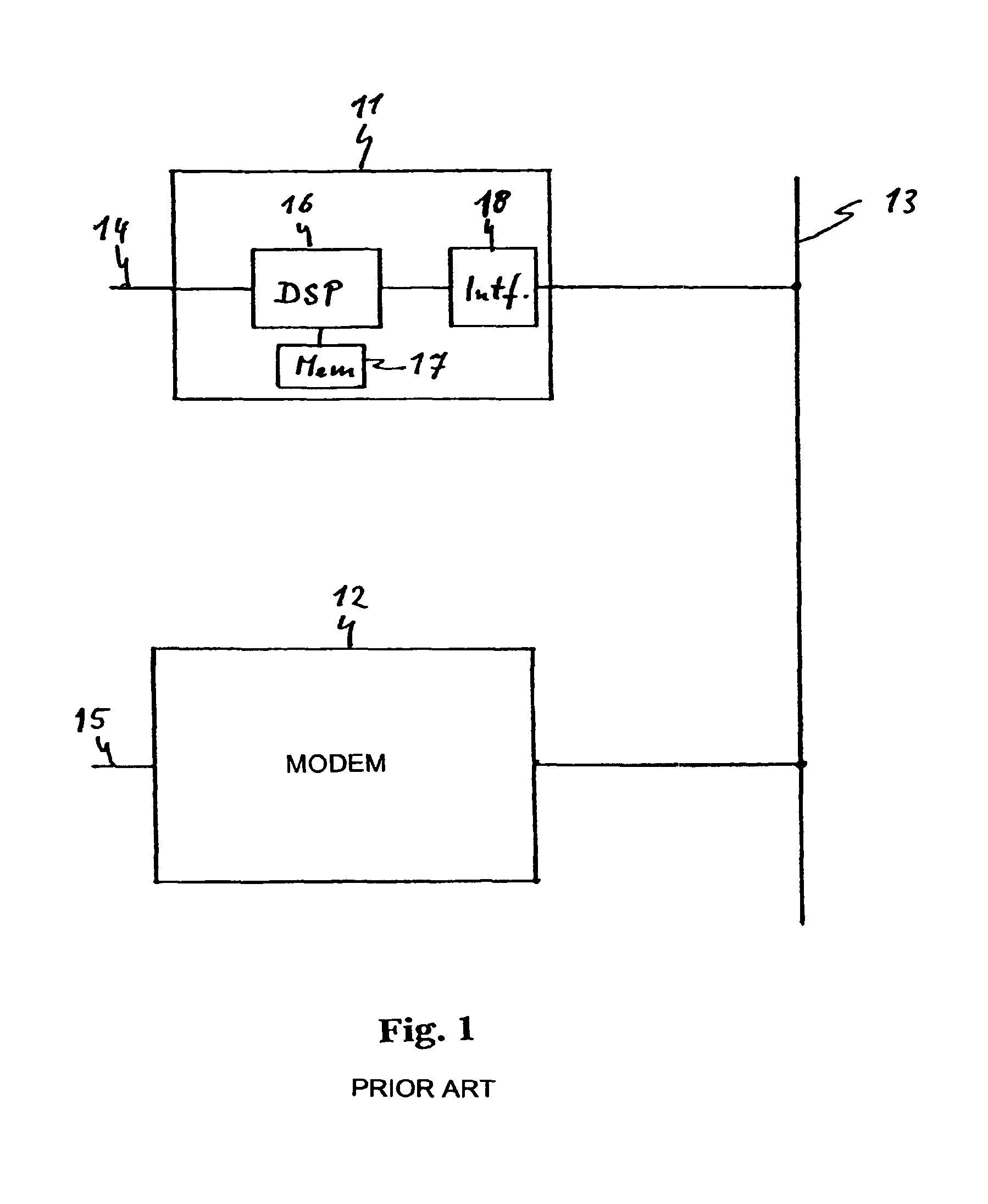
[0039]The system shown in FIG. 1 contains two modems 11, 12 which receive data on an application-side terminal 14, 15 and transmit the data in the form of modulated signals over a powerline network 13. They also receive signals from the powerline network 13, demodulate them and output data contained therein on the application-side terminals 14, 15. Each modem 11, 12 contains a digital signal processor 16 which converts the modulated signals on the powerline network 13 into the data at the application-side terminals 14, 15 and vice versa and operates according to data and a program stored in a memory 17. The digital signal processor 16 is provided with an interface 18 to communicate the modulated signals to and from the powerline network 13 but to separate the digital signal processor from the mains voltage on the powerline network 13.

[0040]Communication on the powerline network 13 is conducted using a multicarrier technique within a transmission channel. A plurality of carrier signa...


PUM


Abstract

Data communication between two devices (11, 12) over the public powerline network (13) uses a multi carrier technology wherein a communication channel is divided into a plurality of subchannels by frequency division multiplexing. A partial power as part of the total transmission power and a partial rate as a fraction of the total data rate are assigned to each subchannel as follows:Initially, the same partial power is assigned to each subchannel and the S / N ratio of each subchannel is obtained. Starting with the subchannel of the lowest S / N ratio and proceeding to that of the highest S / N ratio, the following steps are performed for each subchannel:Firstly, the partial rate is assigned in accordance with the respective S / N ratio such as to result in a predetermined transmission error rate. The assigned partial rate is then quantised to an integral value. If the quantising corresponds to a rounding down, the initially assigned partial power is reduced such that the transmission error rate remains the same as before quantisation. Further, the partial power of other subchannels with higher S / N ratio is increased such that the sum of all partial powers remains constant. Eventually, the increased S / N ratio resulting from increasing the partial power for these subchannels is calculated so that, when the present steps are conducted for them, an optimum partial rate can be assigned to them.This method maximises the total data rate of the entire communication channel while the error rate of each subchannel and the sum of all partial powers remain constant.

Description

FIELD OF THE INVENTIONBackground of the Invention[0001]The invention relates to a method and an apparatus for data communication over a powerline network.[0002]There exist different national and international standards for data communication over the public powerline network, e.g. the low voltage network of 230 V in Central Europe or 110 V in the US. the standards restrict transmission to certain frequency bands and limit the transmission power. To well use a transmission channel within these limitations, the technology of multiple carrier transmission was proposed.[0003]This technology divides a transmission channel into N independent subchannels generally having the same bandwidth, e.g. having in a frequency division multiplexing technique a constant frequency separation between them. The data stream to be transmitted is separated into substreams and transmitted on the subchannels. These technologies are called “Discrete Multitone” DMT, “Multicarrier Modulation” MCM or “Orthogonal...

Claims


Application Information

Patent Timeline
Patent Type & Authority Patents(United States)
IPC IPC(8): H04L27/26H04B3/54H04L1/00H04J1/00H04J11/00
CPCH04B3/54H04L27/2601H04B2203/5495
Inventor TAGER, WOLFGANGPOHL, STEPHANSTOGER, MATTHIAS
Owner POLYTRAX INFORMATION TECH
Why Eureka
Try Eureka