Speaker installation and method

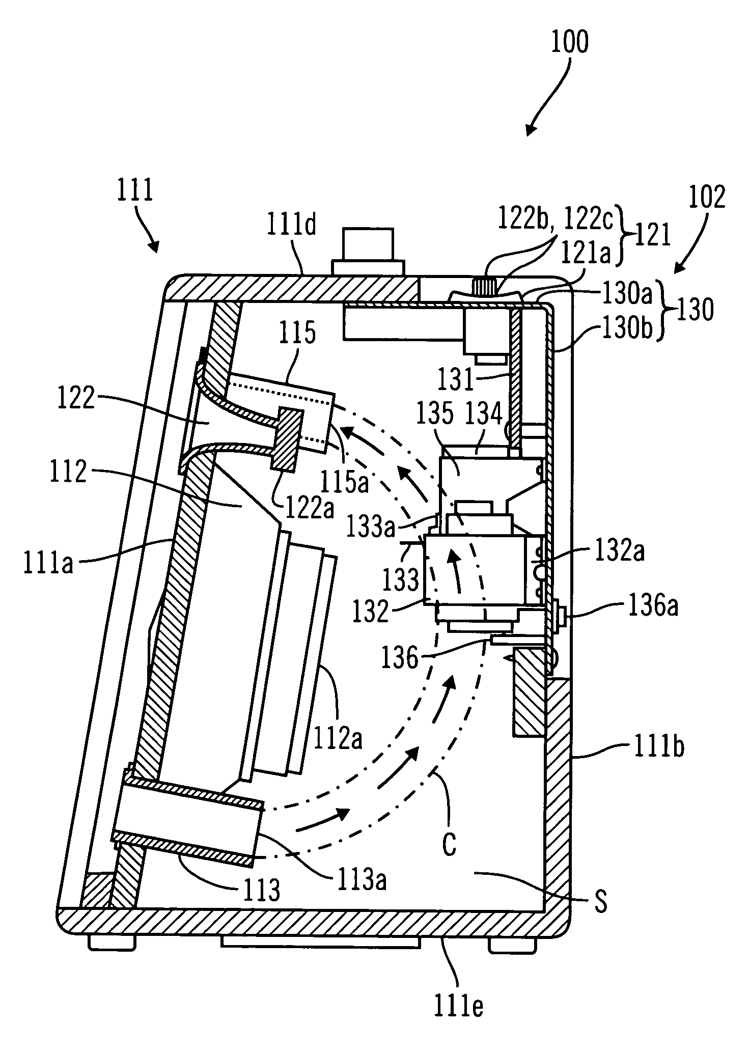
a technology for speakers and speakers, applied in the direction of transducer details, electrical apparatus casings/cabinets/drawers, cooling/ventilation/heating modifications, etc., can solve the problems of insufficient heat radiating ability, failure or faulty operation of speakers, and a large amount of heat produced by power amplifiers, etc., to achieve efficient dissipation of heated air from the speaker box

Inactive Publication Date: 2005-10-18
ROLAND CORP
View PDF8 Cites 30 Cited by
  • Summary
  • Abstract
  • Description
  • Claims
  • Application Information

AI Technical Summary

Benefits of technology

[0012]According to one embodiment of the present invention, a speaker system is provided which comprises a speaker box defining an interior air space and having at least a first surface and a second surface. The speaker system further comprises a speaker arranged within the interior air space. At least one air inflow port on the first surface provides an opening to outside of the speaker box from the interior air space. At least one air outflow port on the second surface provides an opening to outside of the speaker box from the interior air space. A heat producing component such as an amplifier is arranged relative to the speaker within the interior air space such that air entering the interior air space from outside the speaker box via the at least one air inflow port is directed towards the heat producing component to cool the component. Furthermore, heat radiated from the heat producing component rises above the speaker in the interior air space before exiting to outside the speaker box via the at least one air outflow port, thus efficiently dissipating heated air from the speaker box.

Problems solved by technology

However, a considerable amount of heat is produced by the power amplifier when the speaker is driven.
This heat, if it is confined within the box, can undesirably cause failures or faulty operation of the speaker.
Because of that, in those cases where an amplifier has been deployed in the interior air space of the speaker box, there is a problem in that the heat radiating ability is insufficient and the heat cannot be fully radiated.
As a result, there have been failures and faulty operation of components in the speaker box.
In addition, it has been difficult to satisfy the temperature requirements that are prescribed by the safety standards of various countries.
However, in those cases where the area of the opening is made unreasonably large, the acoustic characteristics of the speaker system are impaired.
This creates an unsafe condition for the user.

Method used


Image

  • Speaker installation and method
  • Speaker installation and method
  • Speaker installation and method

Examples


Embodiment Construction

[0023]In the following description of embodiments of the invention, reference is made to the accompanying drawings which form a part hereof, and in which is shown by way of illustration specific embodiments in which the invention may be practiced. It is to be understood that other embodiments may be utilized and structural changes may be made without departing from the scope of embodiments of the present invention.

[0024]As discussed above, the present invention relates generally to a speaker system and, in particular, relates to a speaker system in which both the heat radiation of the power amplifier and satisfactory acoustic characteristics can coexist.

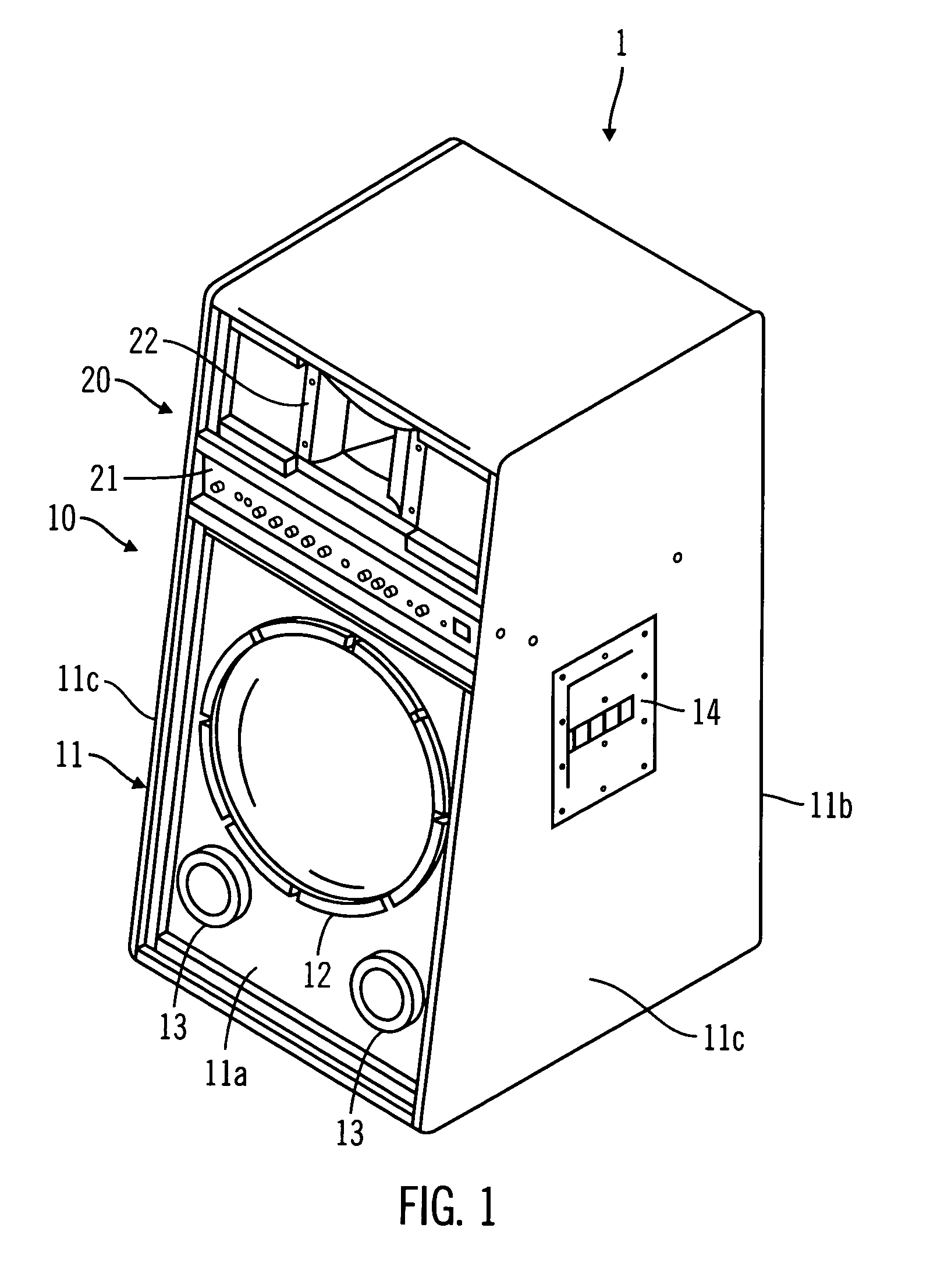
[0025]FIG. 1 is an exterior oblique drawing of a first preferred embodiment of the present invention viewed diagonally from above the front surface of the speaker system 1.

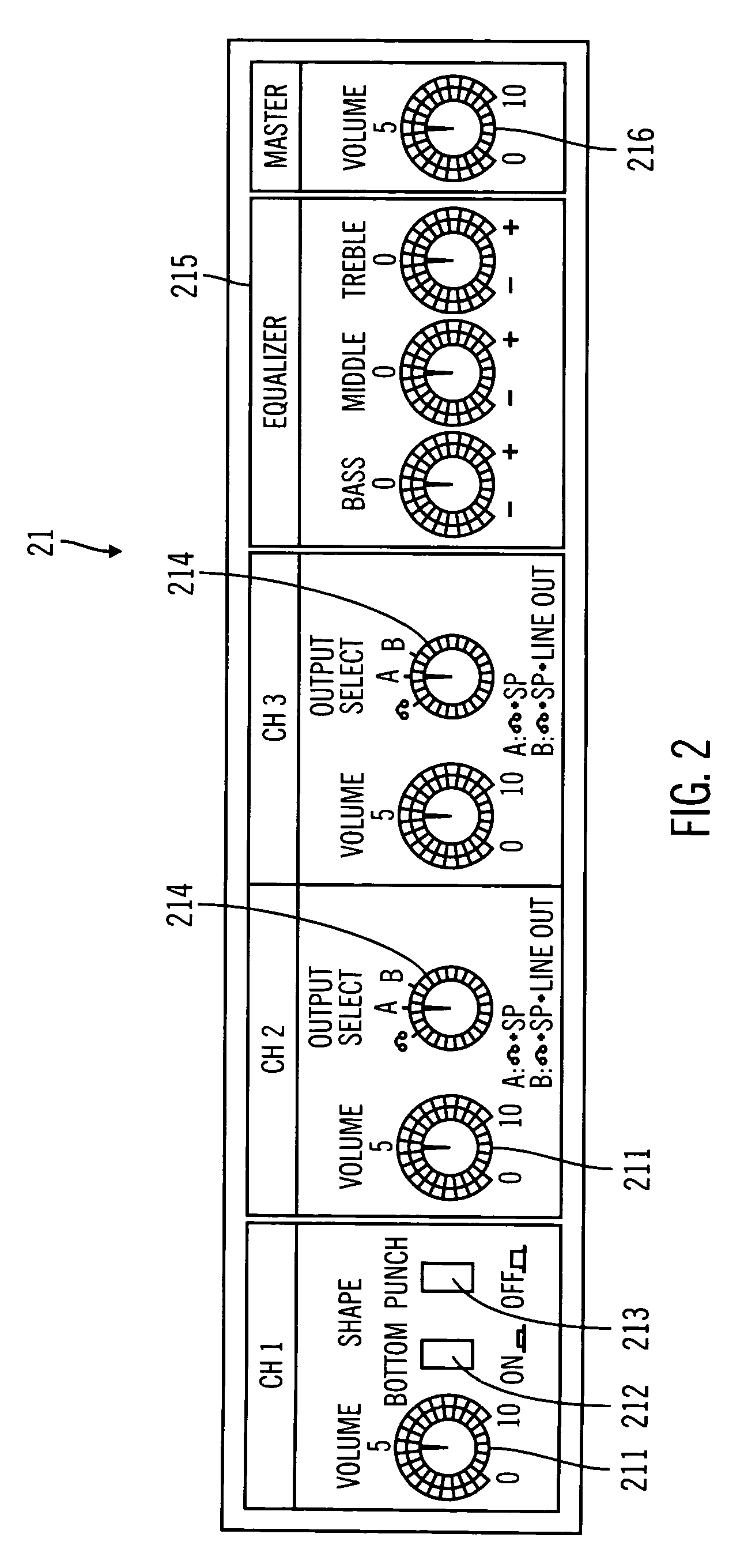
[0026]A speaker system 1, shown in FIG. 1, is a speaker system for use with, for example, an electronic percussion instrument and includes a woofer section 10 and ...


PUM


Abstract

A speaker system in which it is possible for power amplifier heat radiation and satisfactory audio characteristics to coexist. The power amplifier, and other components which are sources of heat, are arranged in an air flow convection path that is formed in a curved path from a lower bass reflex port toward an upper bass reflex port of a speaker box. The heat is exhausted (radiated) to the outside from the interior air space of the speaker box by the air flow and air from outside is introduced into the interior air space with good efficiency. In addition, the power amplifier includes a heat sink. The heat sink includes gaps that are formed between each of a plurality of fins which are opened in a vertical or diagonal direction such that the air flow convection path passes through the gaps.

Description

CROSS-REFERENCE TO RELATED PATENT APPLICATIONS[0001]This application is based upon and claims the benefit of priority from the prior Japanese Patent Application No. 2002-316712 filed Oct. 30, 2002 and Japanese Patent Application No. 2002-64923, filed Mar. 11, 2002, the entire contents of each of which are incorporated herein by reference.BACKGROUND OF THE INVENTION[0002]1. Field of the Invention[0003]The present invention relates generally to a speaker system and, in particular, relates to a speaker system in which both the heat radiation of the power amplifier and satisfactory acoustic characteristics can coexist.[0004]2. Description of Related Art[0005]For some time, speaker systems in which a speaker is mounted in a speaker box having an interior air space formed therein have been known. These speaker boxes may have an opening for heat radiation provided in the front surface of the speaker box. The opening allows the heat that is generated by the speaker to be exhausted to the ou...

Claims


Application Information

Patent Timeline
Patent Type & Authority Patents(United States)
IPC IPC(8): H04R1/02H04R1/28H04R1/00H04R1/26H05K7/20
CPCH04R1/02H04R1/2819
Inventor KURATANI, TOMOAKITAKATA, KOSUKE
Owner ROLAND CORP
Why Eureka
Try Eureka