Satellite receiving converter and satellite receiving system

a satellite receiving and converter technology, applied in the field of satellite receiving converter and satellite receiving system, can solve the problems of increasing customer complaints, affecting the service quality of the customer, and the inability to select the image signal, so as to prevent the amplitude of the control signal from being largely reduced

Inactive Publication Date: 2005-10-18
SHARP KK
View PDF11 Cites 14 Cited by
  • Summary
  • Abstract
  • Description
  • Claims
  • Application Information

AI Technical Summary

Benefits of technology

[0019]The present invention is made in view of the foregoing conventional problems, and an object is to provide a satellite receiving converter which performs receiving operation in response to a control signal supplied from a tuner, and does not cause error operation of an internal circuit by preventing amplitude of the control signal from being largely reduced. The present invention also provides a satellite receiving system adopting the satellite receiving converter.

Problems solved by technology

It may result in error operation so that the desired image signal cannot be selected.
Accordingly, when the switching device 3 or the dividing device 4 are provided, the occurrence of error detection becomes more likely, thereby causing customer complaints even when there is no problems on the LNB1 itself.

Method used


Image

  • Satellite receiving converter and satellite receiving system
  • Satellite receiving converter and satellite receiving system
  • Satellite receiving converter and satellite receiving system

Examples


embodiment 1

[Embodiment 1]

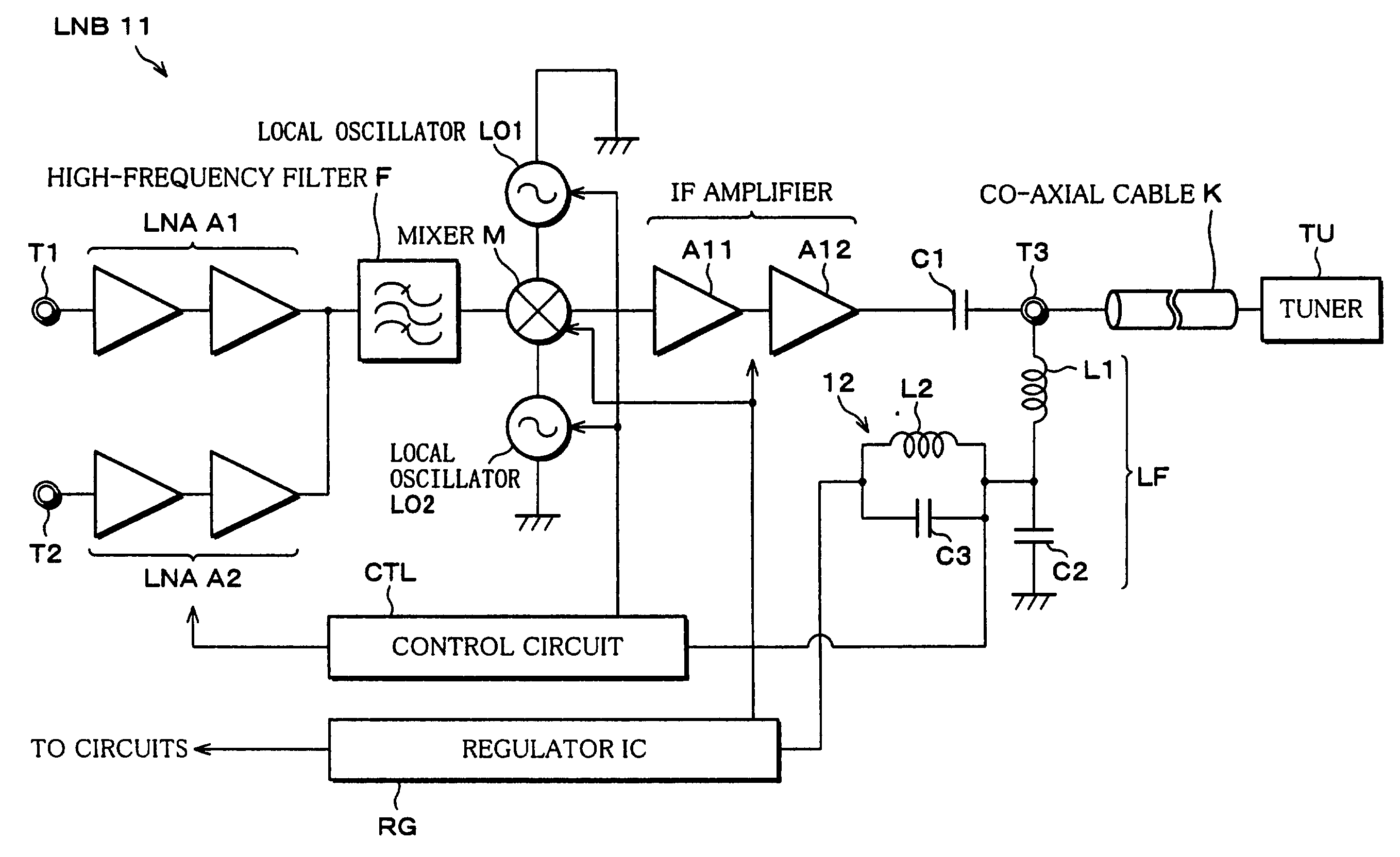
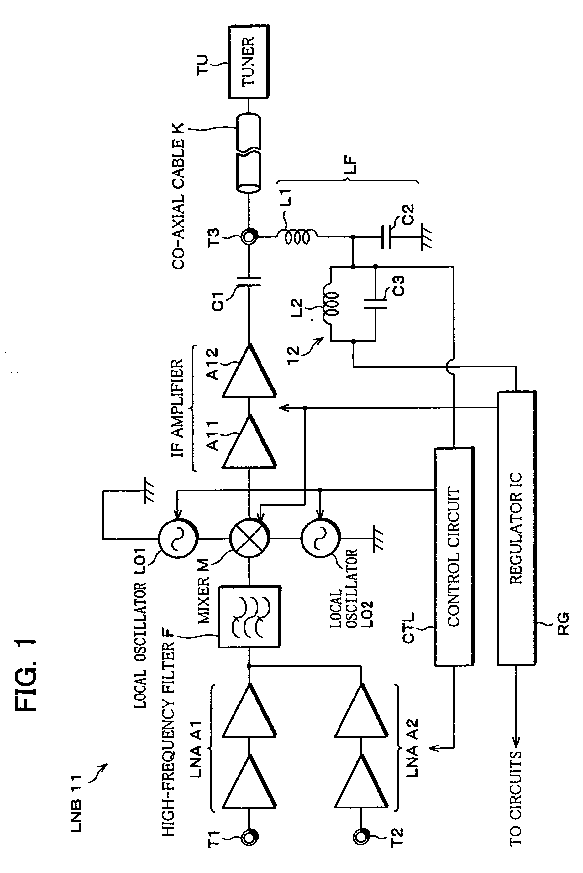
[0040]The following will explain a first embodiment of the present invention with reference to FIG. 1.

[0041]FIG. 1 is a block diagram showing an electrical arrangement of a LNB11 according to the first embodiment of the present invention. In the LNB11, a signal of horizontally-polarized wave is inputted to a terminal T1 and a signal of vertically-polarized wave is inputted to a terminal T2, from a receiving horn (not shown).

[0042]As it will be described later, the inputted signals are respectively amplified by LNAs A1 and A2 which are selectively activated by a control circuit CTL, then are inputted to a mixer M via a common high frequency filter F. Further, a local oscillation signal is inputted to the mixer M from local oscillators LO1 and LO2 which are selectively activated by the control circuit CTL.

[0043]The mixer M downconverts a low-band signal inputted from the terminal T1 or the terminal T2 to an intermediate frequency signal of 950 MHz to 1950 MHz, by mixing ...

embodiment 2

[Embodiment 2]

[0051]The following will explain another embodiment of the present invention with reference to FIG. 2. For ease of explanation, materials having the equivalent functions as those shown in the drawings pertaining to Embodiment 1 above will be given the same reference symbols, and explanation thereof will be omitted here.

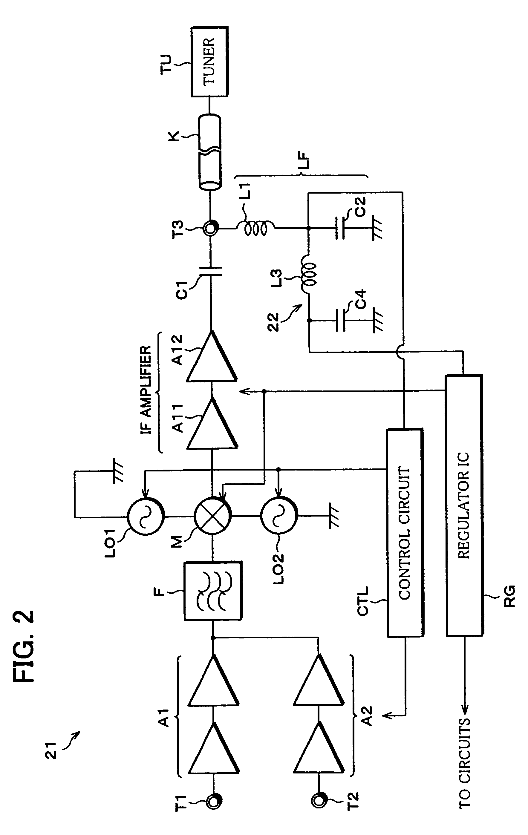
[0052]FIG. 2 is a block diagram showing an electrical arrangement of a LNB21 according to the second embodiment of the present invention. The LNB21 is similar to the described LNB11. The difference between the LNB11 and the LNB21 is an inductor L3 and a capacitor C4 provided instead of the trap circuit 12 of the LNB11. The inductor L3 and the capacitor C4 are respectively provided in series and in parallel between the low-pass filter LF and the input capacitor of the regulator ICRG. The inductor L3 and the capacitor C4 make up a low-pass filter 22.

[0053]With this arrangement, it is possible to increase the impedance XL at the signal input-output terminal...

embodiment 3

[Embodiment 3]

[0055]The following will explain another embodiment of the present invention with reference to FIG. 3. For ease of explanation, materials having the equivalent functions as those shown in the drawings pertaining to Embodiments 1 and 2 above will be given the same reference symbols, and explanation thereof will be omitted here.

[0056]FIG. 3 is a block diagram showing an electrical arrangement of a LNB31 according to the third embodiment of the present invention. The LNB31 is similar to the described LNB21.

[0057]The LNB21 had a single stage low-pass filter 22 made up of the inductor L3 and the capacitor C4; however, the LNB31 has another low-pass filter 22 made up of an inductor L4 and a capacitor C5 in addition to the low-pass filter 22 of LNB21.

[0058]With this arrangement, it is possible to increase the impedance XL at the signal input-output terminal T3 to about 1.4 k Ω. Note that, a larger number of the low-pass filters 22 may suitably be provided.

[0059]Further, also ...


PUM


Abstract

A satellite receiving converter of the present invention performs receiving operation in response to a pulse signal supplied from a tuner. To prevent an amplitude of the pulse signal from being largely reduced in the receiving operation, the satellite receiving converter includes a trap circuit made up of an inductor and a capacitor. The trap circuit is provided after a low-pass filter which divides a pulse signal and a direct-current voltage supplied to a regulator IC. The trap circuit is provided so as to raise impedance with respect to the pulse signal at a signal input-output terminal, thereby preventing error operation of an internal circuit, such as a control circuit.

Description

FIELD OF THE INVENTION[0001]The present invention relates to arrangements of a circuit included in a satellite receiving converter which is realized as a LNB (Low Noise Block downconverter) and a satellite receiving system adopting the satellite receiving converter.BACKGROUND OF THE INVENTION[0002]A LNB is a component attached to the edge of a BS antenna or a CS antenna. The LNB receives a feeble signal of about 12 GHz from a satellite, and amplifies the signal with a low-noise amplifier. Then the LNB converts the signal to an intermediate frequency signal by mixing it with a local oscillation signal in a mixing circuit, and outputs to an external tuner.[0003]FIG. 5 is a block diagram showing an electrical arrangement of LNB1 adopting a typical conventional technology. This LNB1 is destined for Europe. In the LNB1, a signal of horizontally-polarized wave is inputted to a terminal t1 and a signal of vertically-polarized wave is inputted to a terminal t2, from a receiving horn (not sh...

Claims


Application Information

Patent Timeline
Patent Type & Authority Patents(United States)
IPC IPC(8): H04B7/185H04B1/18H04N5/44H04N7/20
CPCH04B7/18517
Inventor IMAI, TAKAO
Owner SHARP KK
Why Eureka
Try Eureka