Fuel tank system

a fuel tank and system technology, applied in the field of fuel tank systems, can solve the problem that the cooling effect cannot be achieved insufficiently, and achieve the effect of efficiently cooling the fuel tank

Inactive Publication Date: 2005-10-25
TOYOTA JIDOSHA KK +1
View PDF30 Cites 38 Cited by
  • Summary
  • Abstract
  • Description
  • Claims
  • Application Information

AI Technical Summary

Benefits of technology

[0024]Thus, if the pressure in the intake system of the engine becomes negative with respect to an internal pressure in the inter-tank-shell space between the inner tank shell and the outer tank shell, air in the inter-tank-shell space is sucked out from the exhaust port through the exhaust pipe. As a result, air flows from the intake port into the inter-tank-shell space through the intake pipe which communicates with at least one of the air cleaner and the cabin. Accordingly, it is possible to efficiently cool the fuel tank by supplying the inter-tank-shell space with at least one of air in the air cleaner and air in the cabin. Also, it is possible to prevent foreign matters from entering the engine intake system by supplying at least one of air in the air cleaner and air in the cabin to the intake system of the engine through the inter-tank-shell space.
[0025]In the aforementioned aspect of the present invention, the intake pipe may be coupled to an evaporator of an air-conditioner. In this construction, it is possible to more efficiently cool the fuel tank by means of the cooling air that has passed through the evaporator of the air-conditioner.
[0026]In the aforementioned aspect of the present invention, intake air control means may be provided. This intake air control means enables air to be sucked through the intake port if the interior of the fuel tank body is higher in temperature than air supplied from the intake pipe. In this construction, only if the interior of the fuel tank body is higher in temperature than the air supplied by the intake pipe, the intake air control means causes intake air to flow from the intake port into the inter-tank-shell space through the intake pipe which communicates with at least one of the air cleaner and the cabin. As a result, it is possible to more efficiently cool the fuel tank.
[0027]In the aforementioned aspect of the present invention, the exhaust pipe may be coupled to the canister. In this construction, the purge effect in the canister can be improved by passing the air that has been warmed by the fuel tank through the canister.
[0028]In the aforementioned aspect of the present invention, a bypass pipe and exhaust pipe switching means may be provided. The bypass pipe bypasses the canister. The exhaust pipe switching means switches an exhaust path to the bypass pipe in at least one case where purge operation has been stopped and where a temperature of exhaust gas flowing out of the exhaust port is equal to or lower than a predetermined temperature. In this construction, in at least one case where purge operation has been stopped and where a temperature of exhaust gas flowing out of the exhaust port is equal to or lower than a predetermined temperature, the exhaust pipe switching means switches the exhaust path to the bypass pipe. Thereby it becomes possible to cool the fuel tank even if the purge operation has been stopped and to prevent the purge efficiency in the canister from deteriorating due to a fall in exhaust temperature.
[0029]In the aforementioned aspect of the present invention, intake pipe switching means may be provided. This intake pipe switching means blows one of air in the air cleaner and air in the cabin that is the lower in temperature to the intake port. Also, the intake pipe may be coupled to both the air cleaner and the cabin. In this construction, it is possible to more efficiently cool the fuel tank by means of one of air in the air cleaner and air in the cabin that is the lower in temperature.

Problems solved by technology

Thus, cooling effect cannot be achieved sufficiently.

Method used


Image

  • Fuel tank system
  • Fuel tank system
  • Fuel tank system

Examples


first embodiment

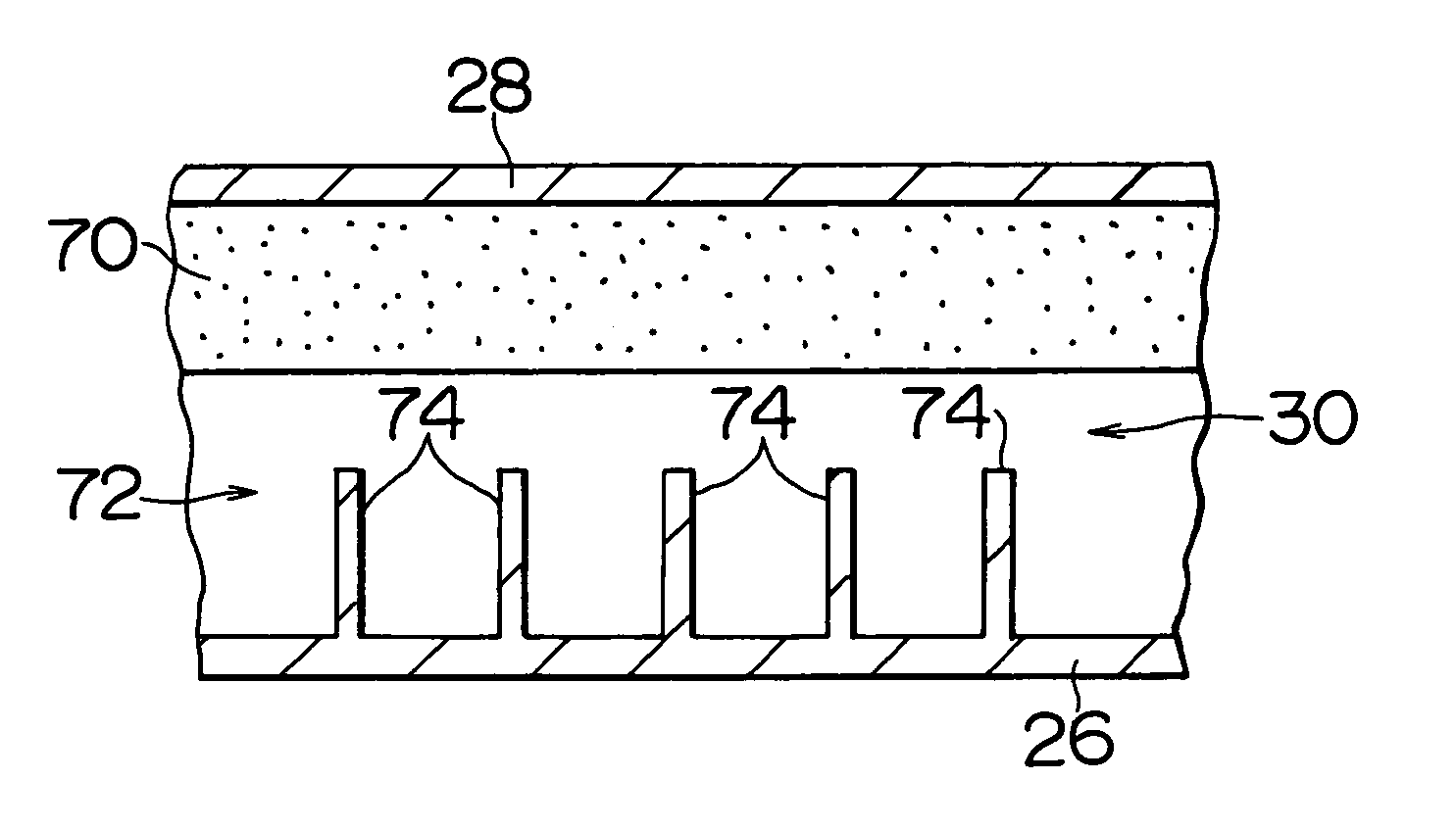
[0038]A fuel tank system in accordance with the present invention will be described with reference to FIGS. 1 and 2.

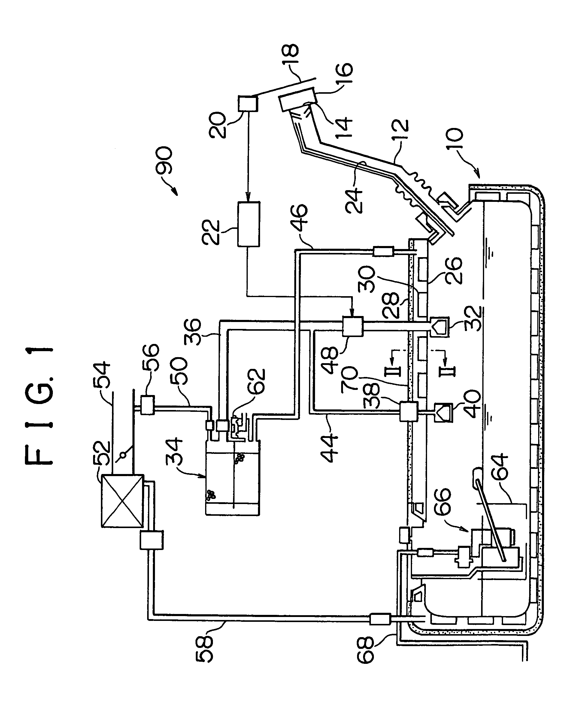
[0039]As shown in FIG. 1, in a fuel tank system 90 of this embodiment, one end of an inlet pipe (a fuel filling pipe) 12 penetrates a lateral wall portion of a fuel tank body 10. The end of the inlet pipe 12 is inserted into the fuel tank body 10. The other end of the inlet pipe 12 reaches a feed oil port 14 provided in a vehicular lateral wall portion.

[0040]A feed oil cap 16 is mounted to the feed oil port 14. In feeding oil, a feed oil gun (not shown) can be inserted through the feed oil port 14 by opening a fuel lid 18 and removing the feed oil cap 16. In feeding oil, if a fuel level in the inlet pipe 12 rises and a sensor attached to the feed oil gun detects a filled-up state, feed oil operation by the feed oil gun is automatically stopped. The fuel lid 18 is equipped with an open-close detection switch 20 for detecting an open or closed state of the fuel lid 18. T...

second embodiment

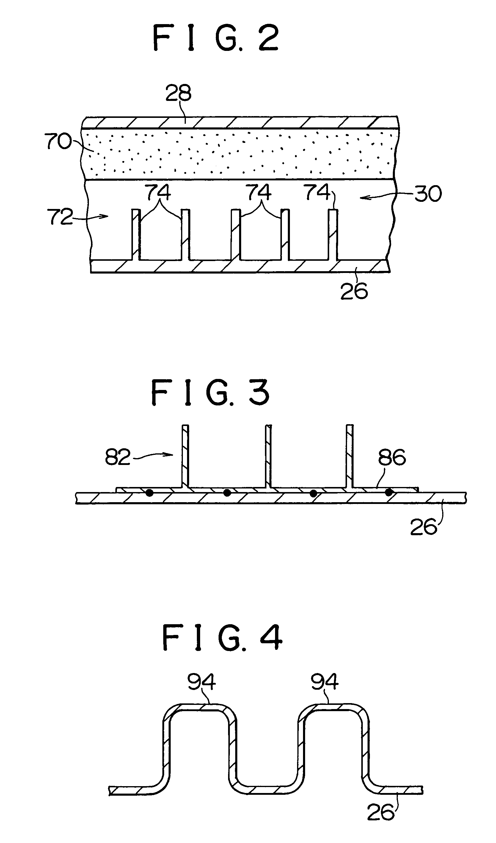
[0058]In the second embodiment shown in FIG. 3, a heat radiation member 82 formed separately from the inner tank shell 26 is mounted to the outer surface of the inner tank shell 26. The heat radiation member 82 is composed of a stationary plate 86 fixed to the inner tank shell 26 and heat radiation fins 84 erected from the stationary plate 86.

[0059]The stationary plate 86 is welded at a predetermined portion and fixed to the inner tank shell 26, whereby the heat radiation member 82 is mounted to the inner tank shell 26.

[0060]Thus, also in the second embodiment, as in the first embodiment, heat of fuel in the fuel tank body 10 is discharged into the inter-tank-shell space 30 through the heat radiation member 82. Thus, fuel in the fuel tank body 10 is prevented from rising in temperature, and generation of vapor is inhibited.

[0061]As long as the heat radiation member 82 can be mounted to the inner tank shell 26, means other than the aforementioned welding can also be employed. For exa...

third embodiment

[0062]In the third embodiment shown in FIG. 4, the periphery of the inner tank shell 26 is generally undulate, so that a plurality of beads 94 are provided in the inner tank shell 26. In this manner, an enlarged surface area of the inner tank shell 26 constitutes heat radiation means.

[0063]Also in the third embodiment, as in the first and second embodiments, heat of fuel in the fuel tank body 10 is discharged into the inter-tank-shell space 30 through the beads 94. Thus, fuel in the fuel tank body 10 is prevented from rising in temperature, and generation of vapor is inhibited. Besides, as in the first embodiment, since heat radiation means (the beads 94) is integrated with the inner tank shell 26, the number of parts does not increase in comparison with the case where heat radiation means is provided separately.

[0064]In this manner, any of the aforementioned embodiments makes it possible to reduce a generation amount of vapor not only by preventing a rise in temperature resulting f...


PUM


Abstract

A fuel tank body has a double-layer structure composed of an inner tank shell and an outer tank shell, so that an inter-tank-shell space is formed therebetween. Because heat of fuel in the fuel tank body is discharged into the inter-tank-shell space, the temperature of fuel in the fuel tank body is prevented from rising. If the pressure in a canister becomes negative due to a negative pressure in an intake system of an engine, more specifically, a negative pressure in a surge tank leading to an air cleaner, high-temperature air in the inter-tank-shell space between the inner tank shell and the outer tank shell flows into the canister. On the other hand, low-temperature air flows from the air cleaner into the inter-tank-shell space which has become negative in pressure.

Description

INCORPORATION BY REFERENCE[0001]The disclosures of Japanese Patent Application Nos. HEI 11-318077 filed on Nov. 9, 1999 and HEI 11-318268 filed on Nov. 9, 1999, including the specifications, drawings and abstracts are incorporated herein by reference in their entirety.BACKGROUND OF THE INVENTION[0002]1. Field of the Invention[0003]The present invention relates to a fuel tank system and, more particularly, to a fuel tank system installed in a vehicle such as an automobile.[0004]2. Description of the Related Art[0005]Some fuel tank systems installed in a vehicle such as an automobile are designed to inhibit a rise in temperature in a fuel tank with a view to reducing the amount of fuel vapor generated in the fuel tank. Japanese Utility Model Publication No. HEI 4-90425 discloses an example of such fuel tank systems.[0006]In a fuel tank system shown in FIG. 7, the periphery of a lower portion of a fuel tank 110 is covered with a heat insulation cover 114 through a heat insulation layer...

Claims


Application Information

Patent Timeline
Patent Type & Authority Patents(United States)
IPC IPC(8): F02M33/00F02M33/02F25B21/02F02M25/08F02M31/20F02M37/10
CPCF02M25/089F02M31/20F02M37/106F25B21/02Y02T10/126Y02T10/12
Inventor KIDO, KATSUYUKIKOBAYASHI, MASAHIDEISHIKAWA, TAKASHI
Owner TOYOTA JIDOSHA KK
Why Eureka
Try Eureka