Hydraulically and volumetrically dispensing fluid

a technology of volumetric and liquid, applied in the direction of positive displacement liquid engine, laboratory glassware, instruments, etc., can solve the problems of time-consuming and labor-intensive cleaning of tubes or conduits, awkward use of some applications, and material residues are typically left behind on the inside wall, etc., to achieve accurate dispense of the target fluid. , the effect of volumetric amoun

Inactive Publication Date: 2005-10-25
NORDSON CORP
View PDF29 Cites 69 Cited by
  • Summary
  • Abstract
  • Description
  • Claims
  • Application Information

AI Technical Summary

Benefits of technology

[0013]In one implementation, a dispensing system includes an actuator, such as a motor or driver, a hydraulic coupler, column or tube that includes substantially incompressible hydraulic liquid, and a mechanical interface to the container or syringe. The actuator may comprise a motor or driver, such as a step motor, linear actuator, servomotor, pneumatic motor, or other similar device, to drive a plunger or piston of the hydraulic coupler. The coupler includes a conduit, column, shaft or other leakproof assembly that acts as a conduit for the substantially incompressible hydraulic liquid. The conduit is connected at one end to a plunger / piston and at the other end to a mechanical interface. The mechanical interface includes a cylinder structure with another plunger or piston that is selectively pushed by the incompressible hydraulic liquid, thereby driving a head of the plunger or piston to press against the wall or plunger of the container or syringe that contains the target fluid, causing the target fluid to be dispensed therefrom. Thus, an actuator selectively provides a force on the hydraulic coupler, which transfers the force to the target fluid to dispense the target fluid from the container. In one implementation, a controller or computer device is coupled to the actuator to accurately dispense a volumetric amount of the target fluid.
[0014]While the methods and processes of the present invention have proven to be particularly useful in the area of dispensing a precise amount of target fluid, those skilled in the art can appreciate that the methods and processes can be used in a variety of different applications and in a variety of different areas of manufacture and / or industry to accurately dispensing a volumetric amount of fluid.

Problems solved by technology

One disadvantage of this technique is that residue of the material is typically left behind on the inside wall of the tube or conduit that must be cleaned.
This requirement of cleaning the tube or conduit can be time consuming and the residue indicates a waste of a portion of the material.
While this technique reduces the requirement for cleaning and reduces the amount of material wasted, it requires the constant pressurizing of water and typically proves to be awkward in use of some applications.
However, a change in atmospheric temperature and / or pressure affects the technique by requiring the system to be adjusted for each given atmospheric modification.
As such, this technique can prove to be time consuming, as it requires the calibration to the various surrounding conditions.
Displacement of the piston or screw creates a positive pressure on a fluid contained in the syringe, thereby causing fluid extrusion from the syringe.
While this technique can dispense a precise amount of material, the apparatus of the hand-held applicator can prove to be bulky and awkward to use.

Method used


Image

  • Hydraulically and volumetrically dispensing fluid
  • Hydraulically and volumetrically dispensing fluid
  • Hydraulically and volumetrically dispensing fluid

Examples


Embodiment Construction

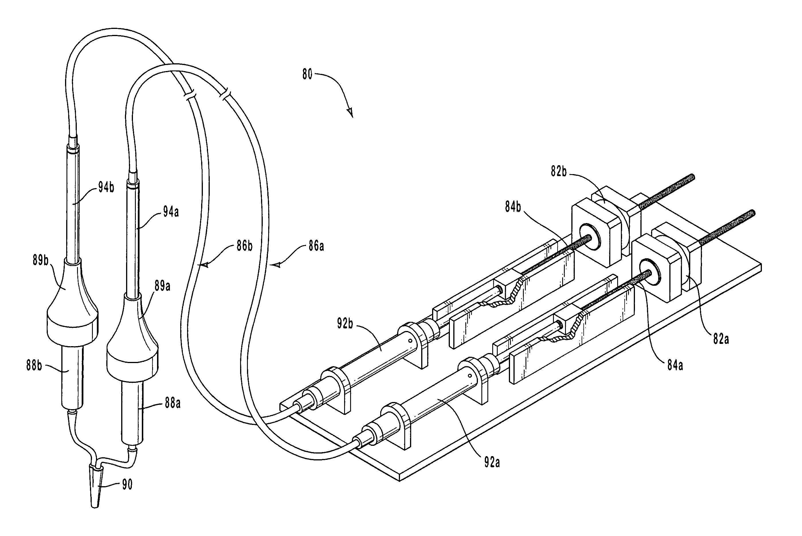
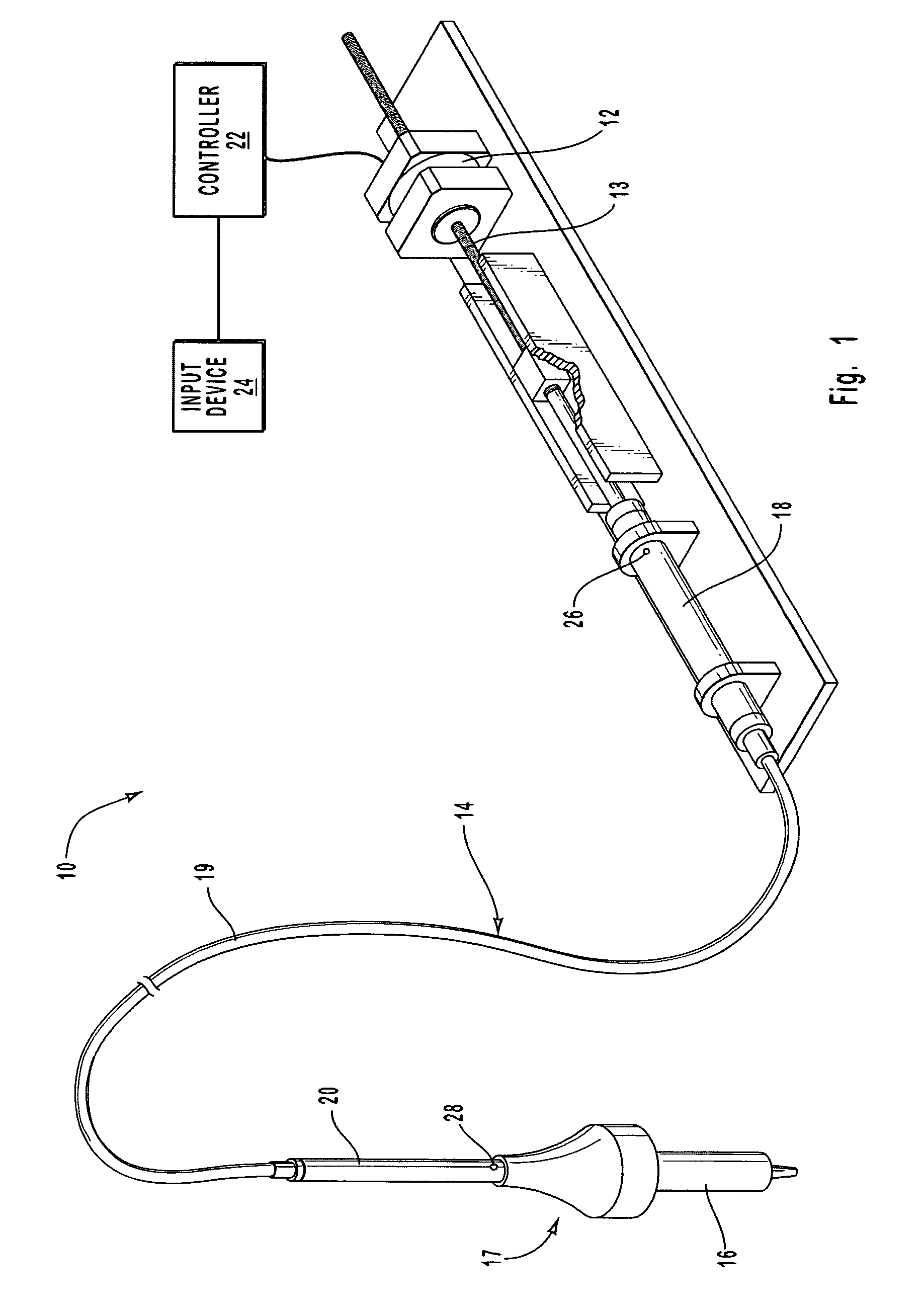
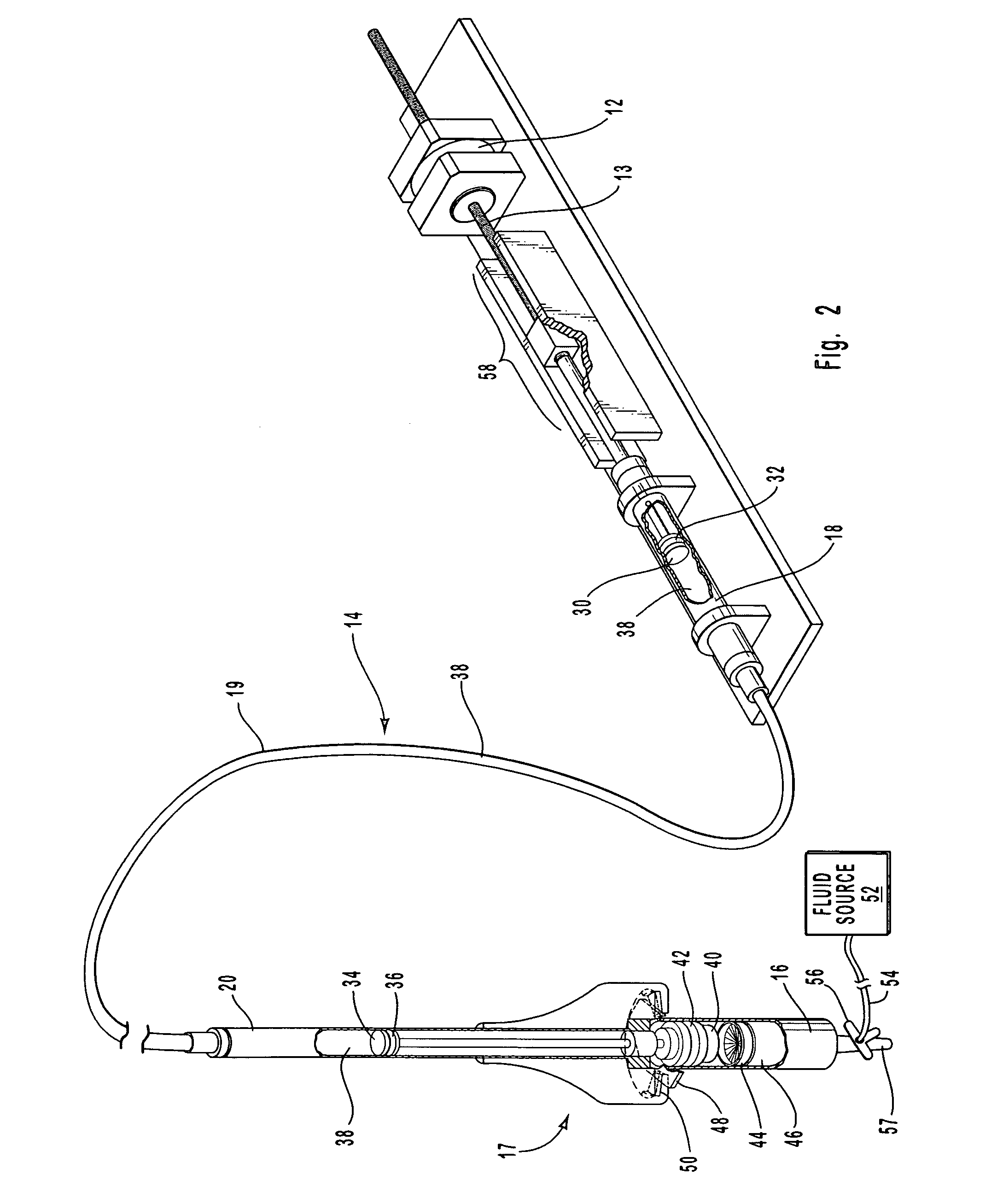
[0023]The present invention relates to hydraulically and volumetrically dispensing target fluid. More particularly, the present invention relates to systems and methods for dispensing a known volume of target fluid through the use of a hydraulic system.

[0024]In the disclosure and in the claims the term “target fluid” shall refer to any material that may be dispensed, whether in a liquid and / or gaseous state. Examples of target fluid include medication, water, oil, grease, paint, adhesive, solvent, lotion, food products (e.g., baby food, condiments, juice, etc.), lubrication, epoxy, silicone, sealant, oxygen, hydrogen, nitrogen, air, and any other liquid and / or gas that have a rheology compatible with being dispensed by physical force. Furthermore, the term “target fluid” shall include materials that are not in a liquid and / or gaseous state, but which may still be dispensed, such as a powder (e.g., graphite), or a paste (e.g., solder paste).

[0025]The following disclosure of the prese...


PUM


Abstract

Systems and methods for hydraulically and volumetrically dispensing target fluid. A hydraulic system includes an actuator, a hydraulic coupler that includes substantially incompressible hydraulic liquid, and a container. The container may include a slidable or movable plunger or wall that when moved forces the target fluid out of the container. The actuator includes a motor or driver, such as a step motor, linear actuator, servomotor, pneumatic motor, or other similar device, to drive a plunger or piston of the hydraulic coupler. The coupler includes a conduit, column, shaft or other leak proof assembly that acts as a conduit for the substantially incompressible hydraulic liquid and includes a plunger or piston that is selectively pushed by the incompressible hydraulic liquid, thereby driving a head of the plunger or piston to press against the wall or plunger of the container or syringe that contains the target fluid or against the target fluid, causing the target fluid to be dispensed therefrom. Furthermore, the system may include a controller that is configured to control the target fluid dispensed and to receive input from a user.

Description

RELATED APPLICATIONS[0001]This application is a continuation of and claims priority to U.S. patent application Ser. No. 10 / 016,970 filed Dec. 14, 2001, now U.S Pat. No. 6,662,969 entitled HYDRAULICALLY AND VOLUMETRICALLY DISPENSING A TARGET FLUID.BACKGROUND OF THE INVENTION[0002]1. Field of the Invention[0003]The present invention relates to hydraulically and volumetrically dispensing fluid. More particularly, the present invention relates to systems and methods for dispensing a known volume of a target fluid, whether liquid and / or gas, through the use of a hydraulic system.[0004]2. Background and Related Art[0005]Historically, a variety of techniques have been employed to dispense materials. Such techniques have included pushing a material through a flexible conduit, using a water control valve to provide pressure to a material, employing a water control valve to dispense the material, and using a hand-held applicator that accommodates a syringe, each of which will be discussed bel...

Claims


Application Information

Patent Timeline
Patent Type & Authority Patents(United States)
IPC IPC(8): F04B13/00G01F11/02B01L3/02
CPCF04B13/00G01F11/021G01F11/029B01L3/0217
Inventor PEELER, SCOTT C.GUEST, BRIAN W.
Owner NORDSON CORP
Why Eureka
Try Eureka