Wallboard rasp

a technology for wallboards and rasps, applied in the field of wallboard tools, can solve the problems of insufficient blade housing for both effective and safe use, affecting the safety of use, and causing sharp edges about the perimeter of metal sheets, so as to eliminate dangerous sharp edges on the blades and prevent inadvertent cuts

Inactive Publication Date: 2005-10-25
WALLBOARD TOOL
View PDF12 Cites 13 Cited by
  • Summary
  • Abstract
  • Description
  • Claims
  • Application Information

AI Technical Summary

Benefits of technology

[0006]The wallboard rasp of the present invention generally includes an expanded metal blade mounted to a molded plastic handle. The handle is configured with a mounting portion having a downwardly-opening receiving groove for receipt of an upwardly-curved perimeter portion of the blade. Because the blade has sharp edges about its perimeter, the groove is formed so as to substantially enclose the free sharp ends of the blade and thereby prevent inadvertent cuts to the worker during use of the rasp. The groove may be formed between a downwardly-projecting outer lip and one or more downwardly-projecting inner ribs so as to be continuous about the handle's underside mounting portion. Also, the corners of the groove and blade perimeter may be rounded to further eliminate dangerous sharp edges on the blade. Where the blade is formed with a substantially planar central portion, the ribs may have substantially planar downwardly-facing surfaces against which the blade's central portion may be supported when mounted on the handle. A lengthwise recess between adjacent ribs provides clearance for cut wallboard material to pass through the blade during use.

Problems solved by technology

Moreover, sharp edges are often created about the perimeter of the metal sheet when the sheet is cut or otherwise configured to the desired size to be mounted on a rasp handle for use.
While these prior art wallboard rasps then serve their intended purpose, they do not optimally house the blade for both effective and safe use.
Rather, the materials and methods of manufacture employed in prior art rasps have resulted in a relatively bulky and more costly tool.
Further, the handles are often configured as elongate bodies that are not conducive to obtaining a good grip on the rasp during use.

Method used


Image

  • Wallboard rasp
  • Wallboard rasp
  • Wallboard rasp

Examples


Embodiment Construction

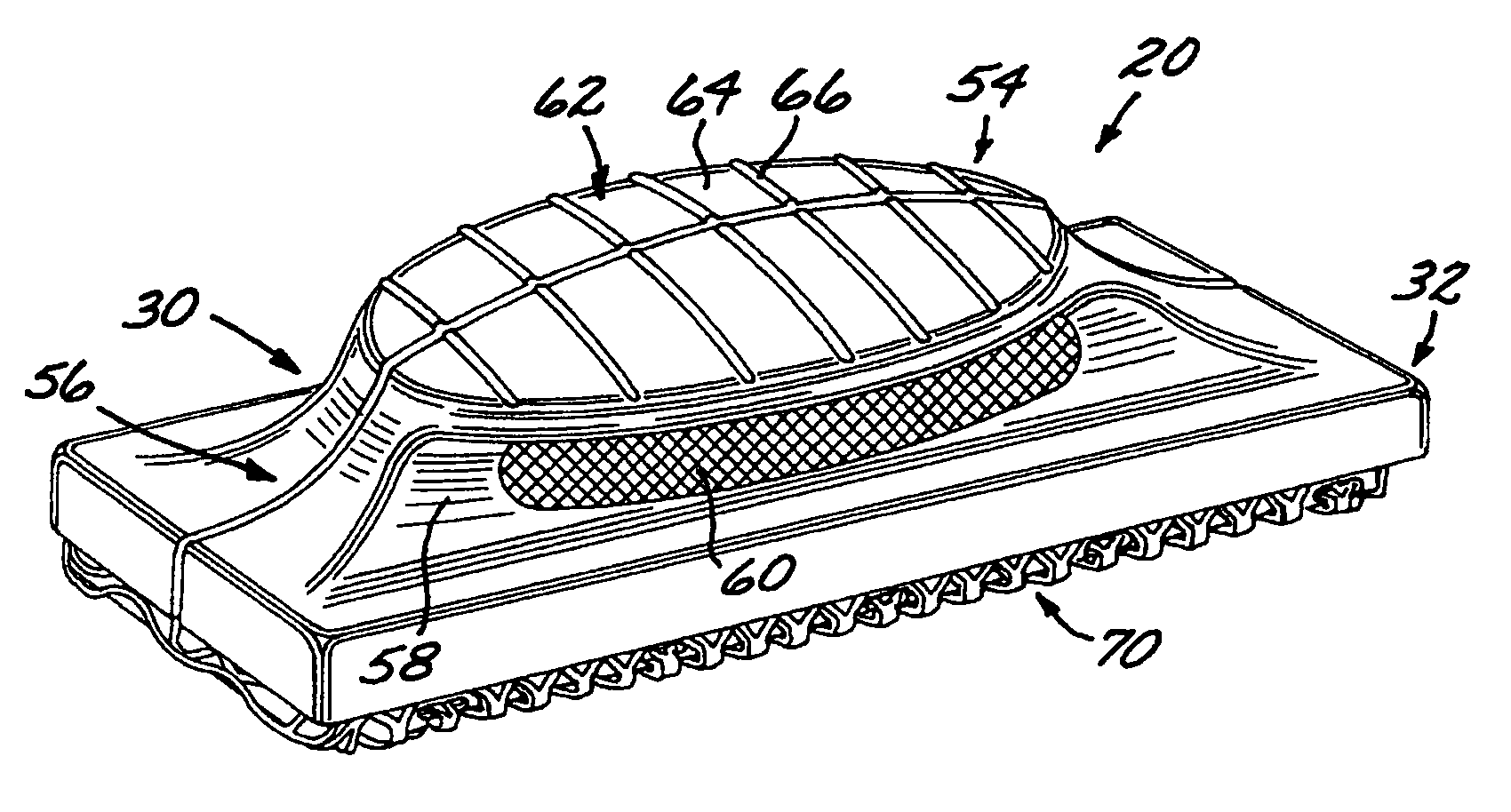
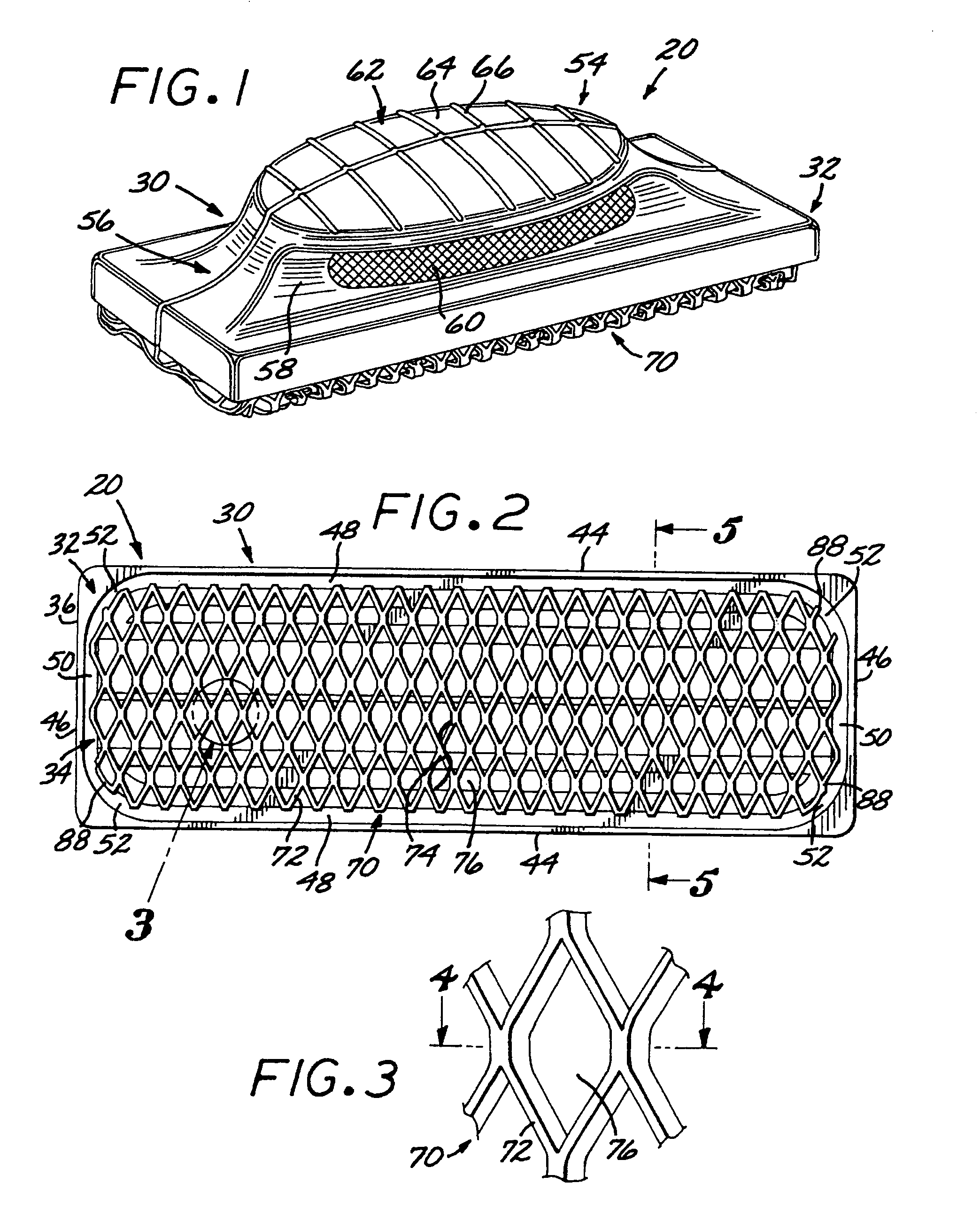
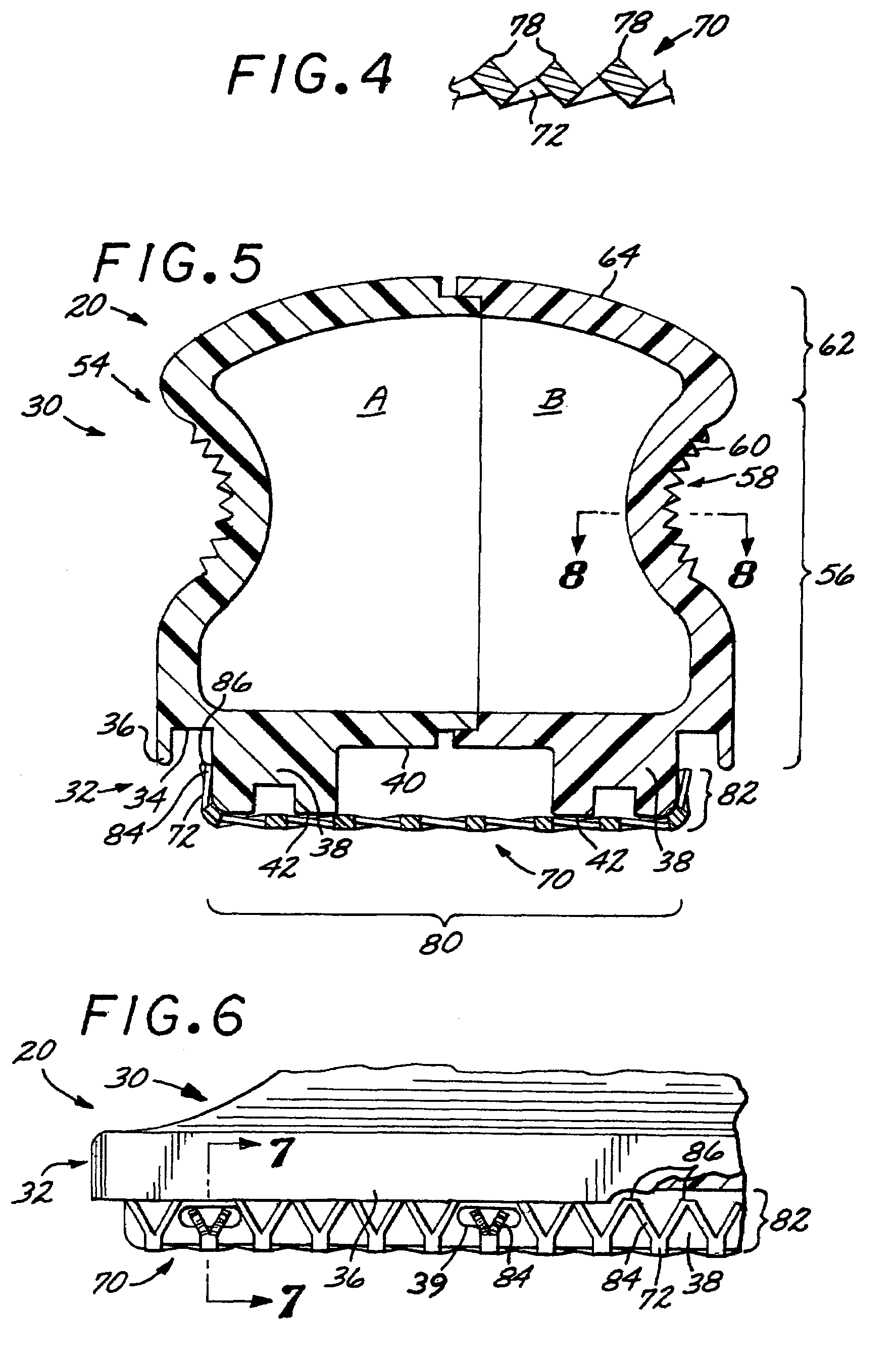
[0019]Referring to the drawings, FIG. 1 shows a perspective view of an exemplary embodiment wallboard rasp 20 of the present invention. The rasp generally includes a molded handle 30 and an expanded metal blade 70 mounted thereon for convenient and safe use of the rasp in reducing and smoothing cut wallboard edges. As discussed in more detail below, the handle has a lower mounting portion 32 configured about its perimeter to receive and enclose the edges 86 (FIG. 5) of the blade and an upper grip portion 54 contoured to provide a comfortable, secure grip on the rasp during use.

[0020]Turning now to FIG. 2, a bottom view of the wallboard rasp 20 shows the expanded metal blade 70 mounted on the underneath, downwardly-facing side of the handle 30. The blade is shown as being formed from a pattern of intersecting metal strips 72 defining a lattice 74 with generally hexagonal openings 76 throughout. This construction allows the blade to be shaped and sized so as to have a perimeter essent...


PUM

PropertyMeasurementUnit
perimeteraaaaaaaaaa
sizeaaaaaaaaaa
dimensionaaaaaaaaaa

Abstract

A wallboard rasp having an expanded metal blade mounted to a molded plastic handle. The handle is configured with a downwardly-opening receiving groove for receipt of an upwardly-curved perimeter portion of the blade. Sections of the blade's perimeter may be crimped or heat staked within the groove. The groove may be formed between a downwardly-projecting outer lip and one or more downwardly-projecting inner ribs. Where the blade is formed with a substantially planar central portion, the ribs may have substantially planar downwardly-facing surfaces against which the blade's central portion may be supported when mounted on the handle. The grip portion of the handle is configured as a contoured, upwardly-extending body having a base with opposite knurled inset surfaces and a convex top flanged surface with spaced-apart grip ribs.

Description

BACKGROUND OF THE INVENTION[0001]The present invention relates generally to wallboard tools and specifically to an improved wallboard rasp for reducing and smoothing the edges of wallboard material.[0002]It is well known in the art of building construction to employ gypsum board, or wallboard, in forming the interior wall and ceiling surfaces of a building. Such wallboard material is typically supplied in large sheets which must often be cut to size in order to position the wallboard properly at corner joints and around doors, windows, and wall and ceiling fixtures. Because a close abutment fit is desirable between the piece of cut wallboard and the adjacent wallboard or other obstruction, those skilled in the art will typically cut the fitted piece to a size slightly larger than the opening in which the piece is to be installed and then reduce the piece's size along one or more of its cut edges until a flush fit is achieved.[0003]As is also known and widely used in the art, a wallb...

Claims


Application Information

Patent Timeline
Patent Type & Authority Patents(United States)
IPC IPC(8): B23D71/04B23D71/00
CPCB23D71/04Y10T407/1825Y10T29/49826Y10T407/18
Inventor MASTERSON, JON A.FLORIO, TIMOTHY J.
Owner WALLBOARD TOOL
Why Eureka
Try Eureka