Microspheres with sacrificial coatings for vaso-occlusive systems

Active Publication Date: 2005-10-25
DFINE INC
View PDF3 Cites 94 Cited by
  • Summary
  • Abstract
  • Description
  • Claims
  • Application Information

AI Technical Summary

Benefits of technology

[0024]The invention provides a method for controllably creating a coagulative volume about an embolic member by (i) controlling the center-to-center distance b

Problems solved by technology

This thermal effect causes denaturation of blood components that results

Method used


Image

  • Microspheres with sacrificial coatings for vaso-occlusive systems
  • Microspheres with sacrificial coatings for vaso-occlusive systems
  • Microspheres with sacrificial coatings for vaso-occlusive systems

Examples


Example

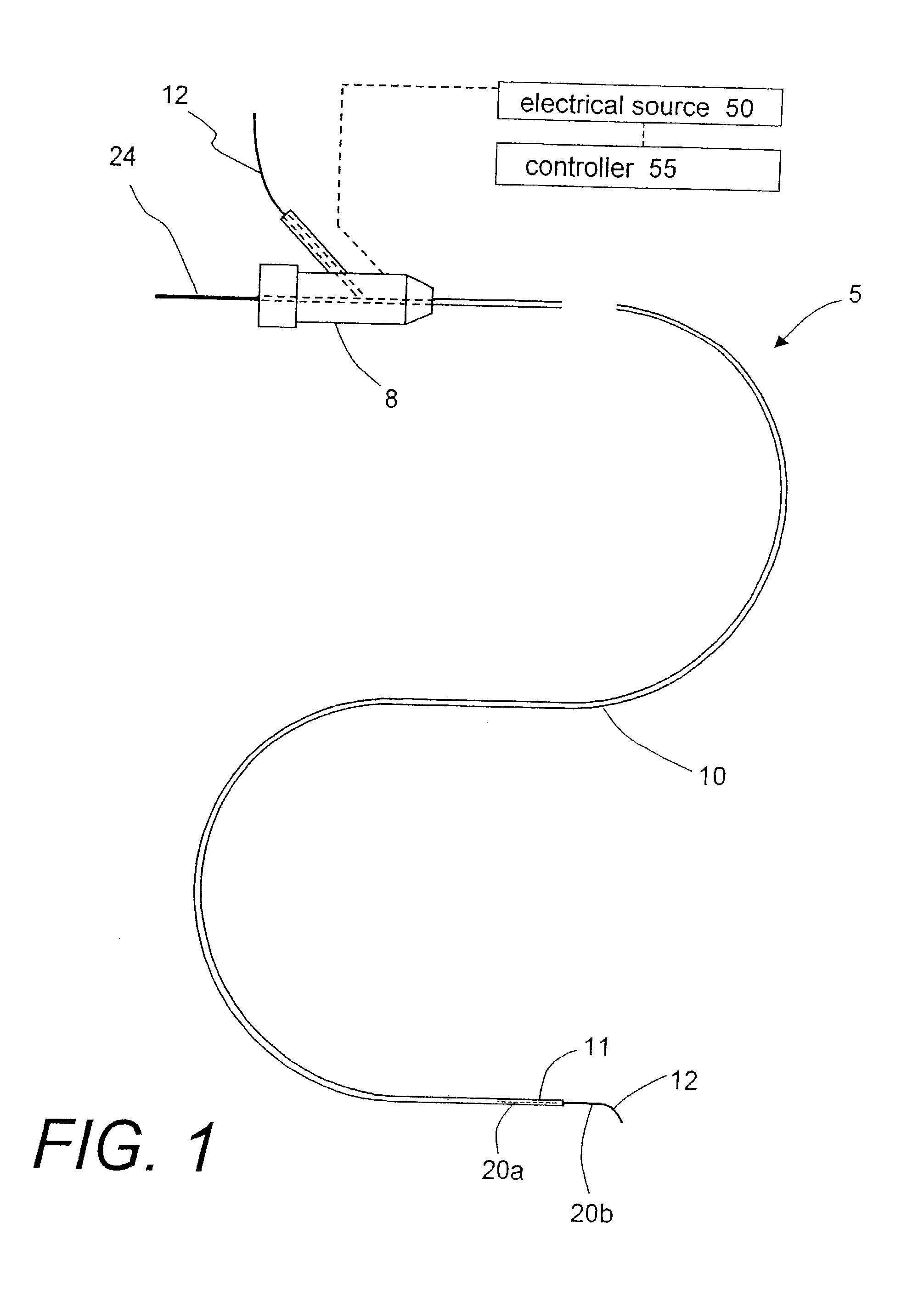
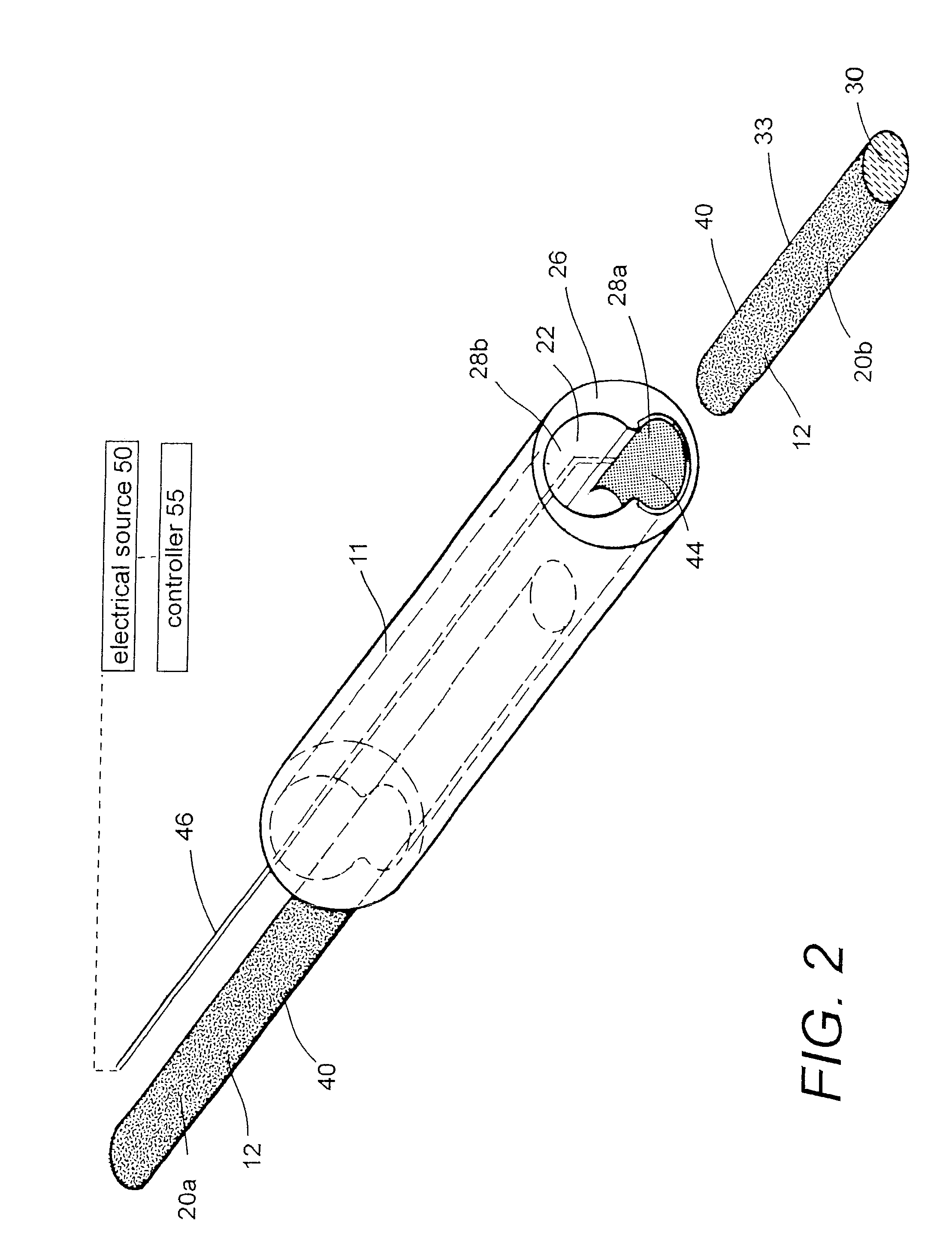
[0050]1. Type “A” embodiment of vascular occlusive system. FIG. 1 shows an elevational view of a Type “A” catheter system 5 for occluding an aneurysm or other vascular malformation. The catheter system has a proximal handle or manifold 8 as is known in the art that is coupled to an elongate microcatheter sleeve 10. FIG. 2 is a cut-away view of the working end 11 of catheter sleeve 10 that illustrates the metallic-coated elongate thread or filament element 12 corresponding to present invention that can be passed axially through the cooperating microcatheter sleeve 10. The flexible embolic element 12 defines a proximal portion 20a still carried within catheter sleeve 10 and a distal thread portion 20b that is pushed outward of the catheter. In this exemplary embodiment, the embolic element 12 has an oval or flattened cross-section, but other cross-sectional shapes are suitable.

[0051]In this exemplary embodiment, an internal bore or passageway 22 within the catheter sleeve 10 is adapte...


PUM


Abstract

A vaso-occlusive system comprising a catheter with a working end that carries a fluid media for introduction into an aneurysm. The fluid media carries a volume of microspheres, wherein each microsphere has a sacrificial shell or coating that surrounds an interior core portion of the microsphere. The core portions of the microspheres comprise either a first or second polymerizing composition, wherein interaction of such binary compositions will cause polymerization of the media into a gel or solid media that will occlude the aneurysm. An energy delivery means is provided within the catheter working end to cause removal of the sacrificial coatings of the volume of microspheres to thereby induce the polymerization process.

Description

CROSS-REFERENCE TO RELATED APPLICATION[0001]This application claims the benefit of Provisional U.S. patent application Ser. No. 60 / 386,544 filed Jun. 5, 2002, having the same title, which application is incorporated hereby by this reference.FIELD OF THE INVENTION[0002]This invention relates to medical systems and techniques for occluding aneurysms. More particularly, the vaso-occlusive provides a fluid media for introduction into an aneurysm that consists of a binary system of microspheres. Each microsphere has a sacrificial coating that surrounds an interior core of the microsphere. The cores of the microspheres comprise either a first or second polymerizing composition, wherein interaction of such binary compositions will cause polymerization of the media into a gel or solid media that to occlude the aneurysm. An energy source is carried at the catheter working end to cause removal of the sacrificial coatings of the microspheres to induce the polymerization process.BACKGROUND OF T...

Claims


Application Information

Patent Timeline
IPC IPC(8): A61B17/12
CPCA61B17/12022A61B17/12045A61B17/12113A61B17/12118A61B17/12136A61B17/12168A61B17/12181A61B17/12186A61B2017/12068
Inventor TRUCKAI, CSABASHADDUCK, JOHN H.
Owner DFINE INC
Why Eureka
Try Eureka