Method for detecting objects and light barrier grid

a technology of applied in the field of methods for detecting objects and light barriers, can solve the problem that the system cannot be impermissiblely manipulated, and achieve the effect of simplifying the setup and adjustment of the system, being more versatile and simple to design

Active Publication Date: 2005-10-25
SICK AG
View PDF16 Cites 26 Cited by
  • Summary
  • Abstract
  • Description
  • Claims
  • Application Information

AI Technical Summary

Benefits of technology

[0021]In one embodiment of the invention the light emitting bar and the light receiving bar each has its own control and evaluation unit. By optically synchronizing the light emitting and light receiving bars, as is described, for example, in DE 38 03 033 A1, no electric connection between the two bars is necessary, which renders the system more versatile and simpler to design.
[0022]By incorporating the control and evaluation unit in the light emitting and / or light receiving bars, the need for an additional unit is eliminated and the entire functionality of the system is integrated into the light barrier grid.
[0023]To eliminate the need for laboriously programming the control criteria, another embodiment of the invention contemplates to provide the control and evaluation unit with means to place the light barrier grid into the learning status. Such means can be a switch or software commands.
[0024]To further simplify the setup and adjustment of the system, the present invention activates the learning phase for the system so that after a predetermined number of objects has traversed the light barrier grid the grid is automatically switched from the learning state to its normal operating state.

Problems solved by technology

Also, the system cannot impermissibly be manipulated because the light barrier grid is active at all times.

Method used


Image

  • Method for detecting objects and light barrier grid
  • Method for detecting objects and light barrier grid
  • Method for detecting objects and light barrier grid

Examples


Embodiment Construction

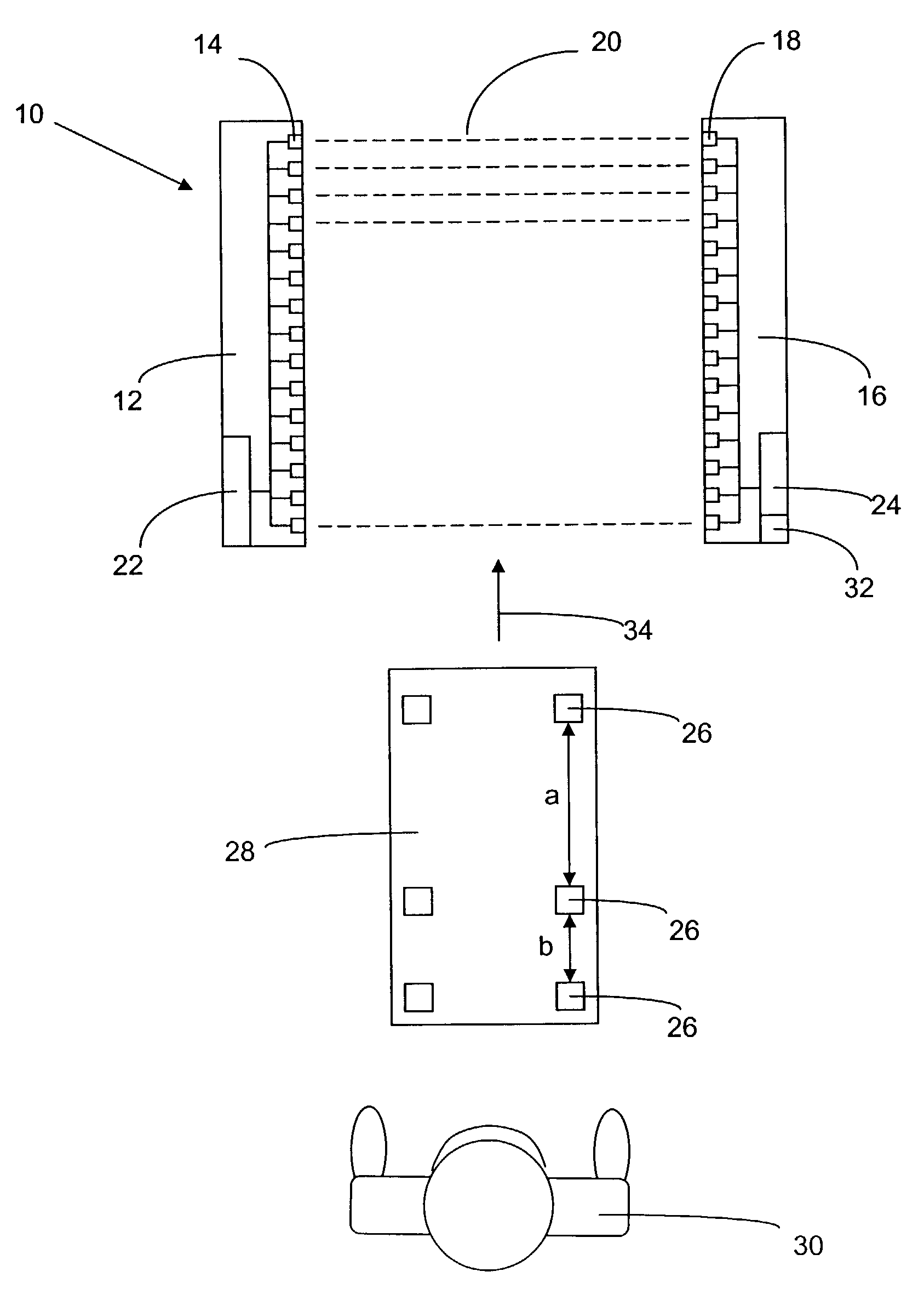
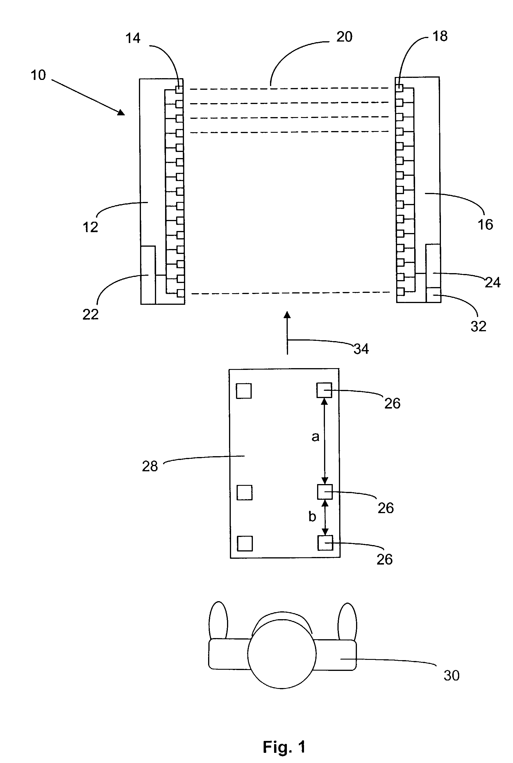
[0027]The light barrier grid 10 of the present invention has a light emitting bar 12 which mounts a number of adjacent light emitters arranged in a row. A light receiving bar 16 has light receptors 18 which correspond to light emitters 14 and which are also arranged next to each other. Respective opposing light emitters 14 and light receptors 18 define a multitude of parallel light barriers 20 in a generally known manner. The light beams between the emitters and the receptors are shown in phantom lines in FIG. 1.

[0028]Thus, light barrier grid 10 with its light barriers 20 defines a control area with a protected space between light emitting bar 12 and light receiving bar 16. In the illustrated embodiment, the light emitting bar 12 and the light receiving bar 16 each have a control and evaluation unit 22, 24. Control and evaluation unit 22 controls the individual light emitters 14 of emitting bar 12, and control and evaluation unit 24 of the receiving bar controls light receptors 18 a...


PUM


Abstract

A method for monitoring two or more movable objects in a monitoring region. A substantially horizontal light barrier grid having a plurality of parallel light barriers monitors the region. To permit a plurality of objects to simultaneously move in the monitored region without deactivating the monitoring function of the system, the system controls an entry area for the objects, the size of the objects as well as the distance between the objects to ascertain that predetermined criteria therefor are met. If one or more of these criteria is not met, a control signal is generated which can be used, for example, to deactivate the machinery and/or prevent access to the monitored region.

Description

BACKGROUND OF THE INVENTION[0001]The present invention relates to a method for identifying two or more movable objects in an observation or monitoring area with an essentially horizontal light grid that has a plurality of parallel light barriers and a light barrier for practicing the method.[0002]Light grids are used, for example, to control highly automated manufacturing systems or assembly lines, such as in the automotive industry, where workpieces are automatically fed to a workstation, worked on and then transported away. Such assembly or manufacturing lines typically have fully automated workstations (for example robot installations) and associated transportation and supply systems. These supply systems and / or the workstations where work is being performed present zones of potential danger for workers which require protection against unwanted intrusions. The desired protection can be provided with light barrier grids of the type described above.[0003]The word “light” as used he...

Claims


Application Information

Patent Timeline
Patent Type & Authority Patents(United States)
IPC IPC(8): G01V8/20G01V8/10G01B11/00G01B11/02G08B13/183
CPCG01V8/20
Inventor HABERER, MANFREDSTAEHLER, THOMAS
Owner SICK AG
Why Eureka
Try Eureka