
Device and method for controlling air volume during idle operation

a technology of air volume control and idle operation, which is applied in the direction of electric control, speed sensing governors, instruments, etc., can solve the problems of unsolved problems, difficult to obtain optimal values for individual gains kp, kd and ki, and difficult to adequately effect these gain change-over or gain map replacements. achieve the effect of considerably facilitating the adjustment of gain k

Active Publication Date: 2005-11-01
MITSUBISHI MOTORS CORP
View PDF4 Cites 14 Cited by
  • Summary
  • Abstract
  • Description
  • Claims
  • Application Information

AI Technical Summary

Benefits of technology

[0013]According to the above-described device, the air volume is controlled based on the target output torque correlation value during the idle operation of the internal combustion engine. It is, therefore, possible to surely stabilize the idle speed of the internal combustion engine during the idle operation.
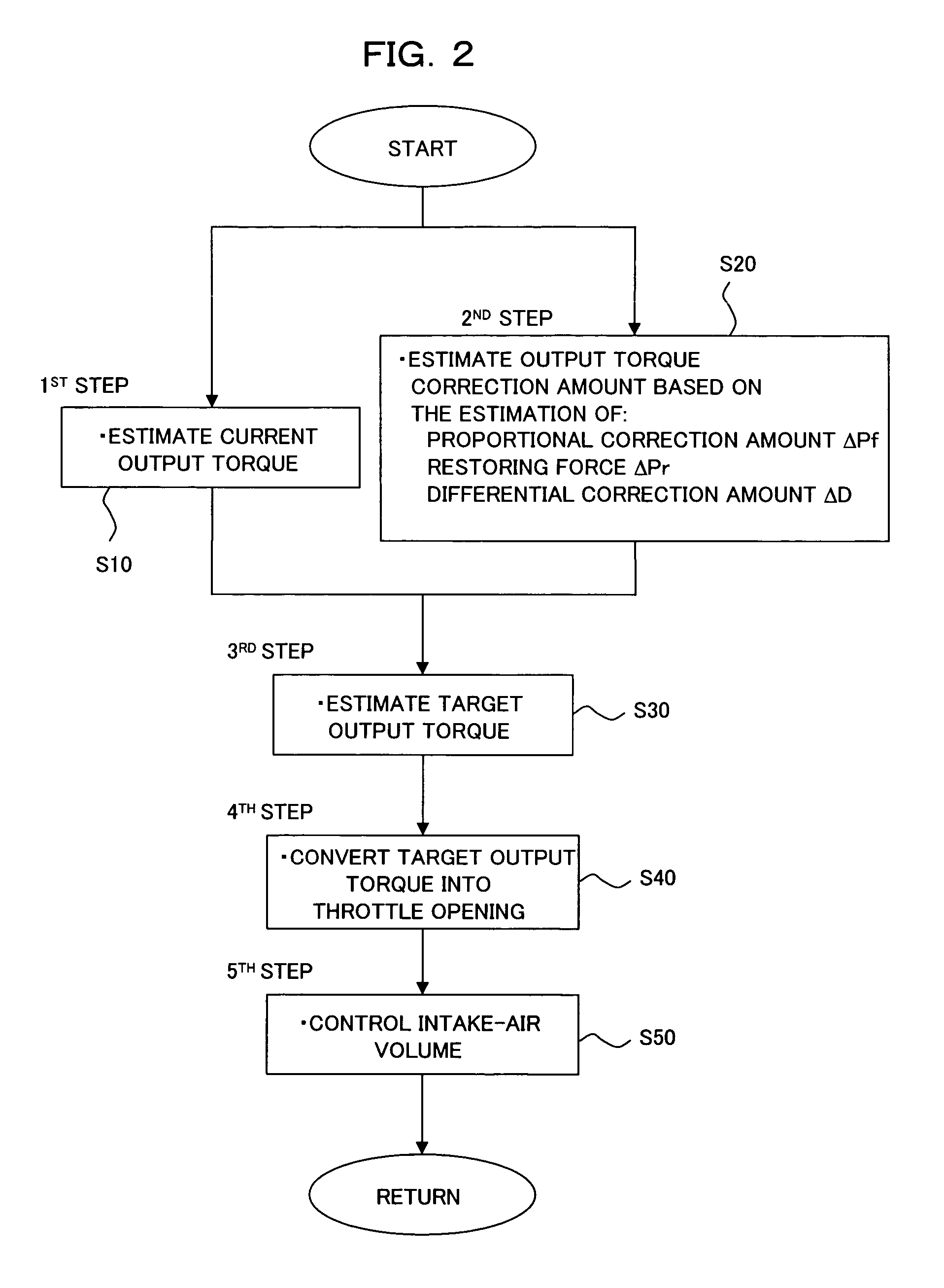
[0035]Preferably, the output torque correlation value to be estimated in the first step can be a throttle opening equivalent to a current output torque corresponding to the present intake-air volume of the internal combustion engine; the output torque correlation value correction amount to be estimated in the second step can be a throttle opening correction amount equivalent to an output torque correction amount corresponding to the difference between the current engine speed and the target engine speed of the internal combustion engine; the third step can estimate a target throttle opening on a basis of a throttle opening equivalent to the current output torque estimated in the first step and the throttle opening correction amount equivalent to the output torque correction amount estimated in the second step; and the fourth step can control the intake-air-volume adjusting system of the internal combustion engine to achieve the target throttle opening estimated in the third step. As the air amount is controlled based on the target throttle opening during the idle operation of the internal combustion engine, the idle speed of the internal combustion engine can be surely stabilized during the idle operation.

Problems solved by technology

It is, however, difficult to obtain optimal values for the individual gains Kp, Kd and Ki because they are generally determined as a result of trial and error upon development of the internal combustion engine.
Even if one tries to effect gain change-over or gain map replacements, it is difficult to adequately effect these gain change-over or gain map replacements.
These problems still remain unsolved in stabilizing an idle speed.
Even in the above-described technique, however, no improvements have been achieved in the setting of the individual gains Kp, Kd and Ki, so that it is still difficult to adequately set the individual gains Kp, Kd and Ki.
However, the technique such as that disclosed in JP 7-197828 A estimates a target throttle opening on the basis of a map so that an accurate target throttle opening can be hardly estimated when the load conditions and atmosphere conditions change, although this technique is free of the difficulty in setting a gain that has remained as an unsolved problem to date.

Method used


Image

  • Device and method for controlling air volume during idle operation
  • Device and method for controlling air volume during idle operation
  • Device and method for controlling air volume during idle operation

Examples


first embodiment

[First Embodiment]

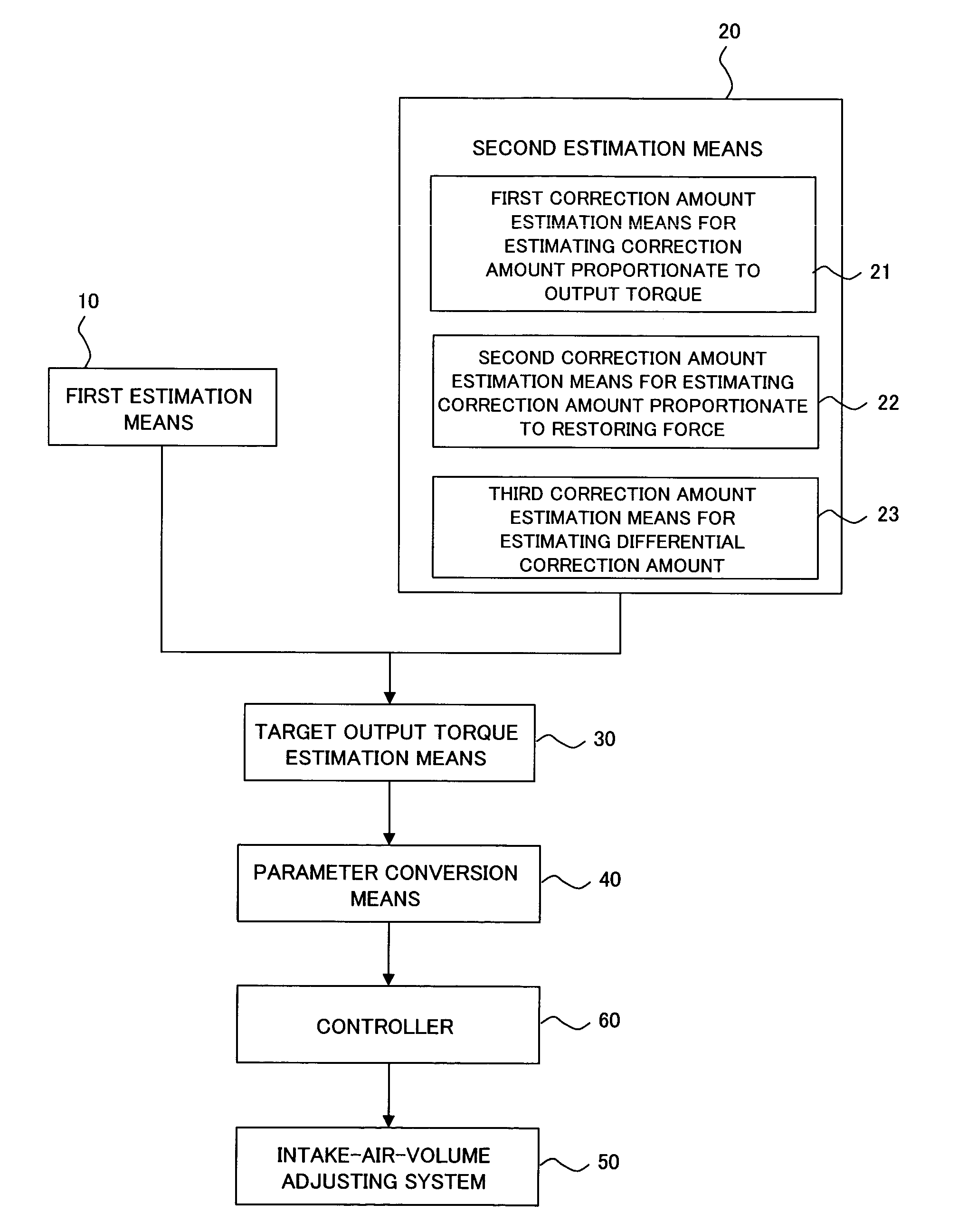
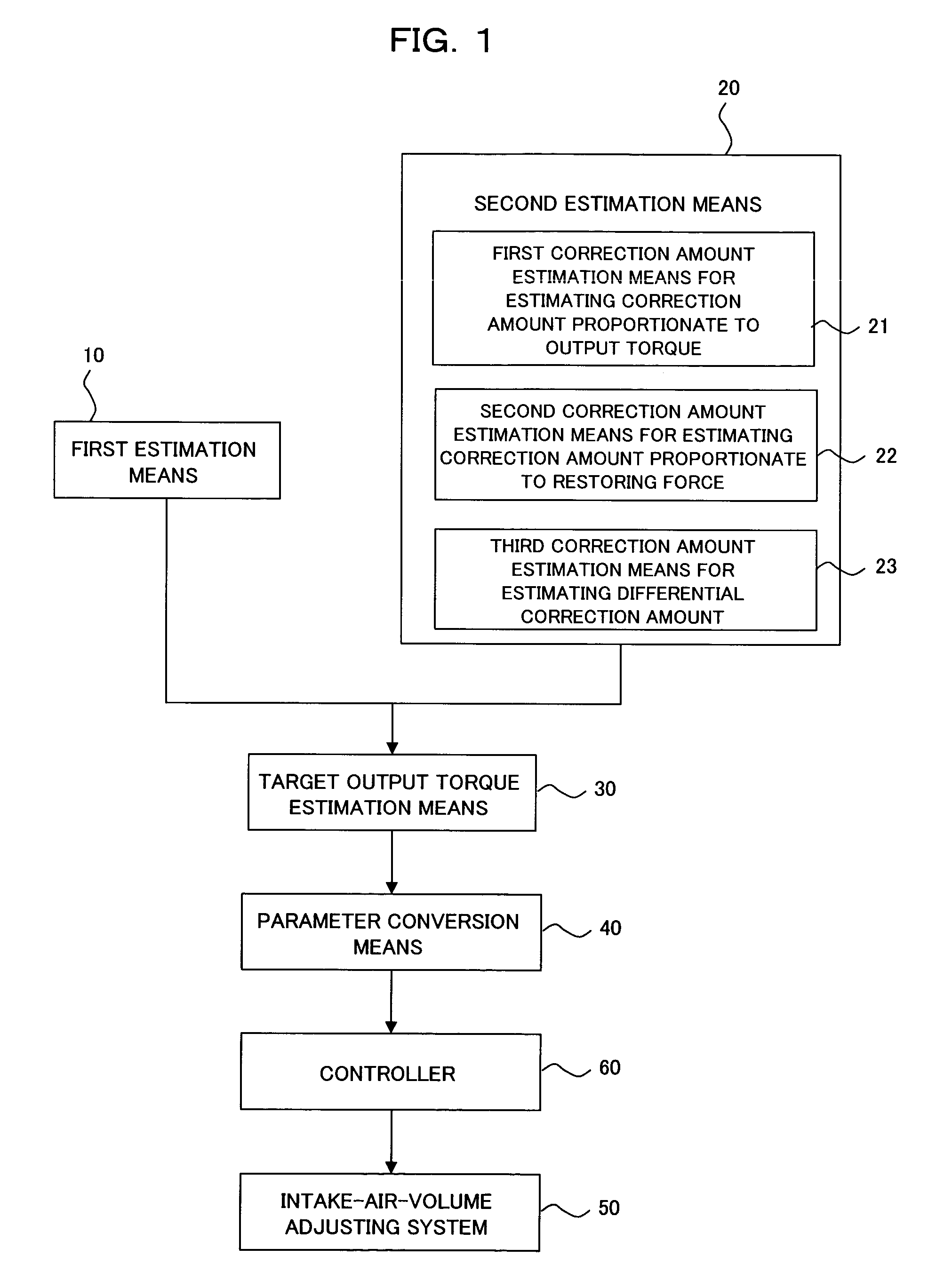
[0041]Firstly, a description will be made about the device and method according to the first embodiment of the present invention for controlling an air volume during an idle operation. FIGS. 1 and 2 show the control device and method according to the first embodiment of the present invention, and FIG. 1 is an overall construction diagram of the control device while FIG. 2 is a flow chart of the control method.

[0042]As shown in FIG. 1, the control device according to this embodiment is constructed of first estimation means 10 for estimating a current output corresponding to a present intake-air volume (which may hereinafter be simply called an “air volume”) of an internal combustion engine idle-operated on the basis of a target engine speed (target rpm); second estimation means 20 for estimating an output torque correction amount (correction value) corresponding to a difference between a current engine speed and the target engine speed; target output torque estimati...

second embodiment

[Second Embodiment]

[0092]A description will next be made about the device and method according to the second embodiment of the present invention for controlling an air volume during an idle operation.

[0093]The control device according to this embodiment is similar to the above-described first embodiment except that, even when the engine speed changes, a restoring force ΔPr to be estimated at the second correction amount estimation means 22 in the second estimation means 20 is not produced immediately but is estimated as an actual restoring force ΔPr involving a response delay. Descriptions of the elements of construction and their functions, which are common to both of the embodiments, are omitted accordingly.

[0094]Referring now to FIG. 1 of the above-described first embodiment, a description will be made about the control device according to the second embodiment. In this embodiment, those elements of the control device which are the same as or equivalent to corresponding elements ...

third embodiment

[Third Embodiment]

[0102]Next, a description will be made about the device and method according to the third embodiment of the present invention for controlling an air volume during an idle operation. FIGS. 3 and 4 show the control device and method according to the third embodiment of the present invention, and FIG. 3 is an overall construction diagram of the control device while FIG. 4 is a flow chart of the control method.

[0103]In the control device according to this embodiment, a current output torque is used at the below-described first estimation means 100 upon estimating a throttle opening as an output torque correlation value equivalent to the current output torque. This current output torque is similar to the output torque Y(n) estimated at the first estimation means 10 in the first embodiment. Further, a proportional correction amount ΔPf, restoring force ΔPr and differential correction amount ΔD are used as output torque correction amounts at the below-described second est...


PUM


Abstract

To permit easy and adequate setting of a gain in an internal combustion engine (hereinafter be called an “engine”) for the surer stabilization of an idle speed, the present invention provides a device for controlling an air volume during an idle operation of the engine. This device is provided with a first estimation unit for estimating a current output torque correlation value corresponding to a present intake-air volume of the engine; a second estimation unit for estimating an output torque correlation value correction amount corresponding to a difference between a current engine speed and a target engine speed of the engine; a third estimation unit for estimating a target output torque correlation value based on the correlation value and the correction amount; and a control unit for controlling an intake-air-volume adjusting system of the engine to achieve an intake-air volume which is equivalent to the target output torque correlation value.

Description

[0001]This Non-provisional application claims priority under 35 U.S.C. § 119(a) on Patent Application No(s). 2003-182732 filed in JAPAN on Jun. 26, 2003, the entire contents of which are hereby incorporated by reference.BACKGROUND OF THE INVENTION[0002]1) Field of the Invention[0003]This invention relates to a device and method for controlling an air volume during an idle operation of an internal combustion engine such that an intake-air volume of the internal combustion engine can be adjusted to stabilize an engine speed of the internal combustion engine during the idle operation.[0004]2) Description of the Related Art[0005]Under conventional idle speed control of an internal combustion engine, which may hereinafter be called an “engine”, of a vehicle or the like to stabilize an engine speed during an idle operation that the internal combustion engine is idling under no-load conditions (in other words, under an internal load alone), a throttle valve or bypass valve (for example, an...

Claims


Application Information

Patent Timeline
Patent Type & Authority Patents(United States)
IPC IPC(8): F02D41/08F02D41/18F02D9/02F02D45/00F02D41/16F02D31/00F02D35/00F02D41/14
CPCF02D31/003F02D35/0023F02D41/1497F02D2041/1409F02D2200/0404F02D2200/1012F02D2250/18
Inventor UEDA, KATSUNORIHANDA, HIDEYUKINAKAMORI, KENICHI
Owner MITSUBISHI MOTORS CORP
Learn More