Fire collar

a technology of fire collar and intumescent material, which is applied in the direction of pipe elements, functional valve types, bore tools, etc., can solve the problems of slowing down the passage of fluid along the pipe or duct, fire can still spread to the other side of the partition, and too long time taken for the intumescent material to form a seal

Inactive Publication Date: 2005-11-01
IG6
View PDF12 Cites 15 Cited by
  • Summary
  • Abstract
  • Description
  • Claims
  • Application Information

AI Technical Summary

Benefits of technology

[0010]In one form of the invention, the heat detector can be formed from a material which has the dual properties of, firstly, being capable of bonding or interlocking with an element of the damper arrangement and the housing and, secondly, being able to yield its bond or lock when it is heated to a predetermined temperature value. These properties enable the heat detector to be designed and located in such a manner that it will normally ensure that the damper arrangement is held open but when a predetermined, ie. preset, temperature is reached, it will yield enabling the damper arrangement to close.
[0013]In another form, the heat detector material can comprise an alloy pad formed on the end of a bearing shaft which extends through the wall of the housing to a location within the damper arrangement, preferably at a location which does not impede the flow of fluid through the housing. A spiral spring retained in a recess on the outer side of the housing connects the shaft to the housing. The spring is normally held under compression and is only released from compression when the alloy pad yields upon being heated to the preset temperature, thereby enabling the shaft and damper to rotate to a closed position.

Problems solved by technology

A major problem with this type of fire collar is that the time taken for the intumescent material to form a seal can be too long in rapidly advancing fires with the result that the fire can still spread to the other side of the partition.
However, although such an arrangement enables very quick sealing to occur, it has the disadvantage that it slows down the passage of fluid along the pipe or duct.

Method used


Image

  • Fire collar
  • Fire collar
  • Fire collar

Examples


Embodiment Construction

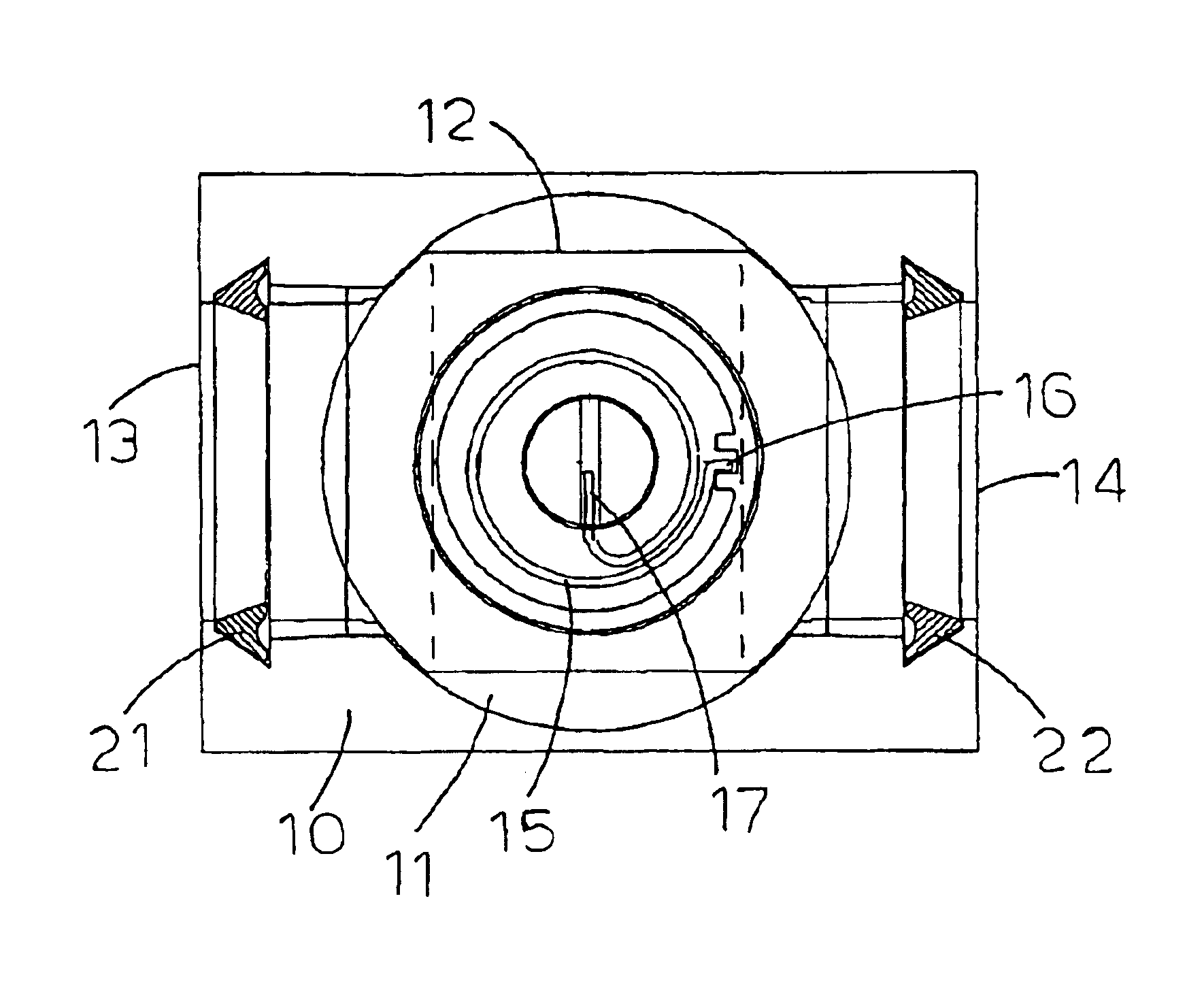
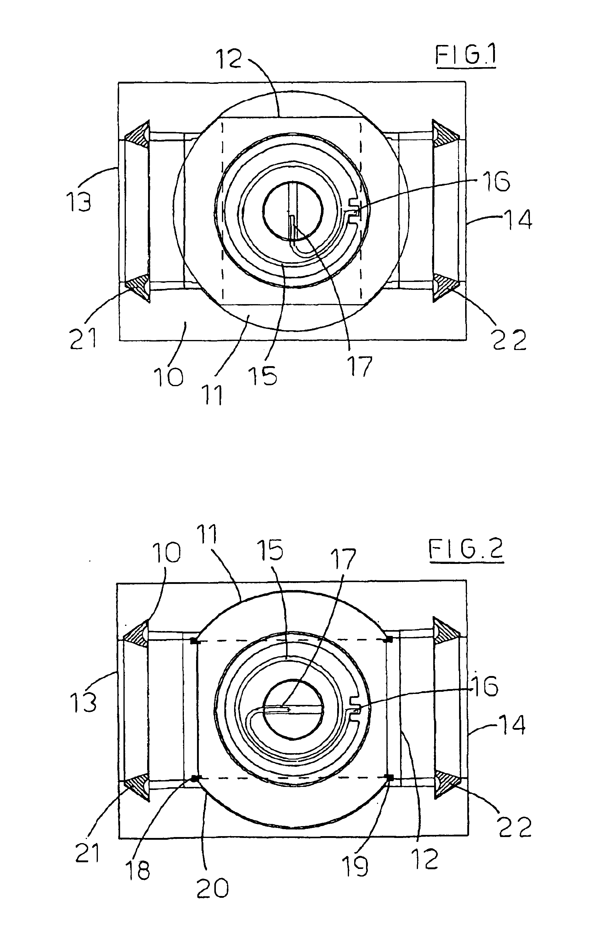
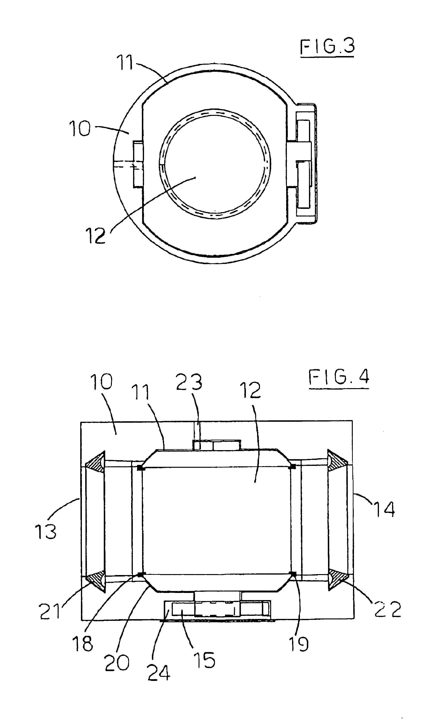
[0008]Preferably, the damper arrangement incorporates a cylinder or ball valve having an internal passageway which is of the same or similar diameter to that of the pipework or ducting in which it is fitted. The cylinder or ball valve is arranged so as to be rotatable about an axis so that it can rotate between a normal open position where passage of fluid through the pipework or ducting is unimpeded to a position, generally at right angles to the open position, where passage of fluid to prevented.

[0009]Rotation of the cylinder or ball valve can be achieved by mechanical and / or electrical means. Mechanical rotation can be, for instance, by the use of a spiral spring retained in a recess formed in an exterior wall of the housing, having its outer end held by the housing and its inner end held by the cylinder or ball valve. In its normal configuration, the spring is under tension but it cannot rotate the ball or cylinder to a closed position until the heat detector reacts to a preset ...


PUM


Abstract

A fire collar or fire damper for location within a concrete slab of a building. The device incorporates a damper arrangement (12) and a heat detector (18, 19) comprising a metal alloy or lead which melts when a preset temperature is reached, causing the damper arrangement to seal off associated pipework or ducting.

Description

FIELD OF THE INVENTION[0001]This invention relates to a device for preventing fire from spreading from one side of a partition to another by way of pipework or ducting in the partition. In particular, the invention is primarily concerned with a new form of fire damper and a fire collar for location in a concrete slab separating the floors and walls of multi-floor buildings.BACKGROUND OF THE INVENTION[0002]A common type of fire collar comprises a metal collar which is fastened around a concrete slab-penetrating plastics material pipe in the region where it traverses the slab; the collar enclosing an intumescent material. When a fire on one side of the concrete slab reaches a sufficient intensity to melt the pipe where it penetrates the slab, it also causes the intumescent material to expand and seal off the void left by the melted pipe. In this way, a barrier is formed to prevent the spread of the fire to the other side of the concrete slab.[0003]A major problem with this type of fir...

Claims


Application Information

Patent Timeline
Patent Type & Authority Patents(United States)
IPC IPC(8): A62C2/06A62C2/00F16L5/02F16L5/04F16L55/10A62C2/24A62C2/12
CPCA62C2/065F16L5/04F16L55/1022F16L55/1026Y10T137/1797Y10T137/1819Y10T137/1963
Inventor TRUSS, JAMES WALTER GEORGE
Owner IG6
Why Eureka
Try Eureka