Oil sealant-preserving drain odor trap

Inactive Publication Date: 2005-11-01
FALCON WATERLESS TECH INC
View PDF38 Cites 28 Cited by
  • Summary
  • Abstract
  • Description
  • Claims
  • Application Information

AI Technical Summary

Benefits of technology

[0022]These and other problems are successfully addressed and overcome by the present invention, which comprises a unitized oil-sealed odor trap that departs from conventional pr

Problems solved by technology

Beetz' requirement for daily cleaning and maintenance dictates an easily-disassembled-three piece structure with a leakage-prone bottom interface joint, and this requirement for the sealant to also act as a disinfectant is n

Method used


Image

  • Oil sealant-preserving drain odor trap
  • Oil sealant-preserving drain odor trap
  • Oil sealant-preserving drain odor trap

Examples


Embodiment Construction

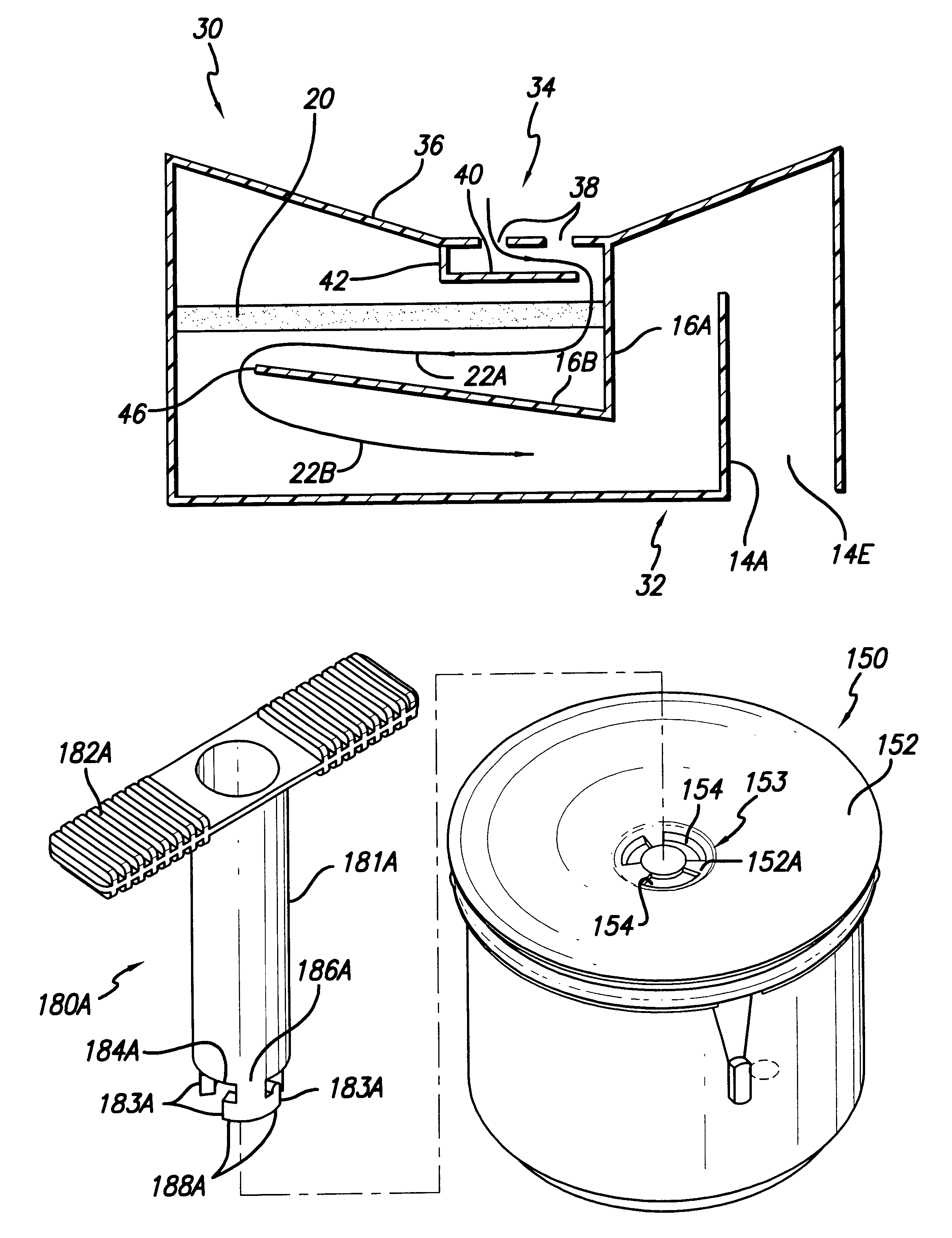
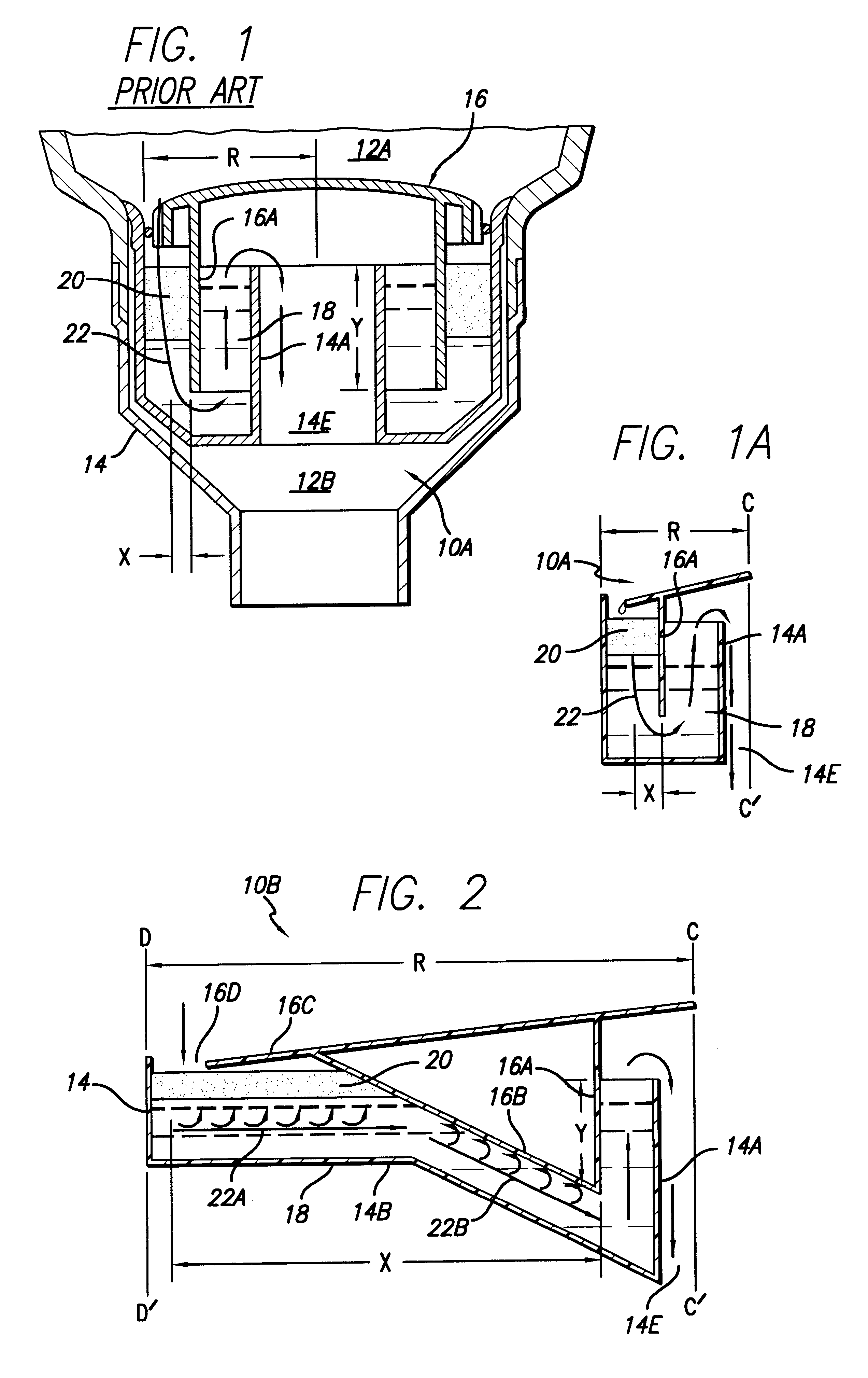
[0048]FIG. 1 is a mid cross-sectional view of an odor trap 10A of the edge-entry trap configuration of known art as described above, and configured as a cylindrical cartridge.

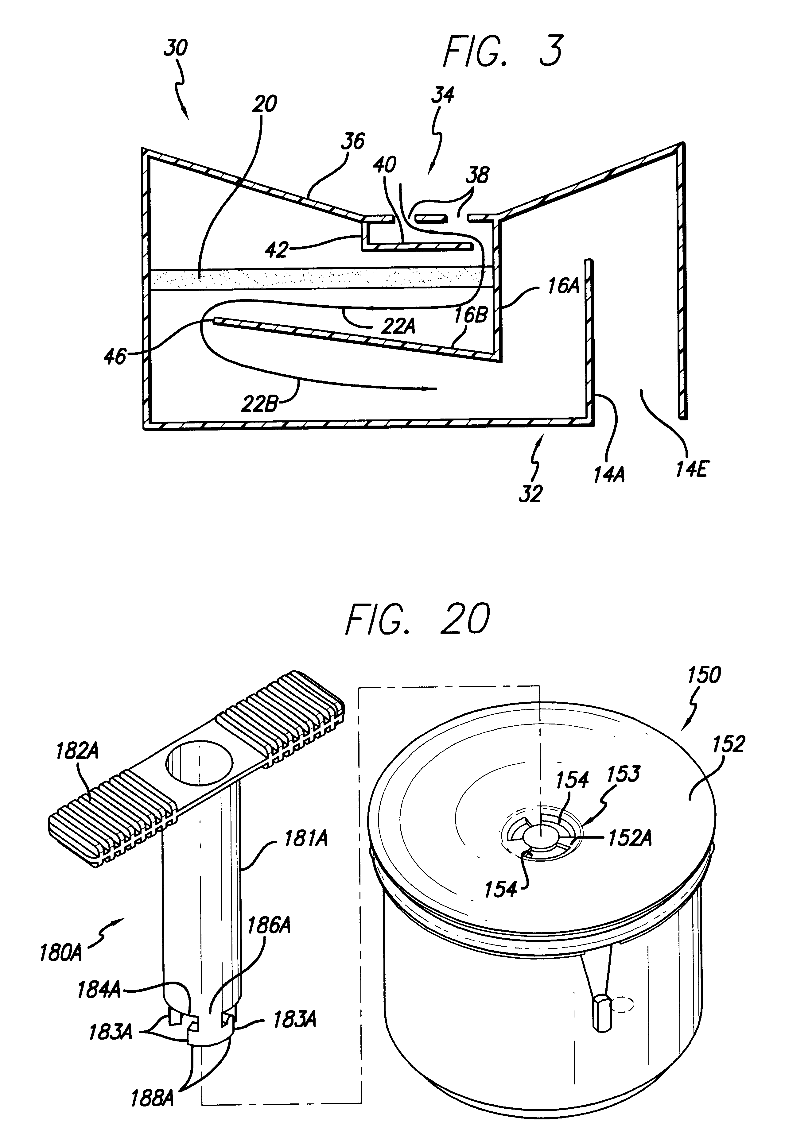
[0049]Odor trap 10A has a main liquid container 14 extending from an outer wall to an inner wall that forms a drain stand pipe 14A which defines, at its upper edge, the overflow level of liquid in the container 14. An overhead cap portion 16 is formed to provide a vertical baffle 16A which extends down into container 14 and divides it into an inner discharge compartment and a surrounding entry compartment. A body of residual urine 18 extends up to the overflow level at the top of stand pipe 14A and, in conjunction with the overhead plenum region formed by the cap portion 16, the residual body of urine 18 serves to trap sewer gasses from the external drain line in accordance with plumbing codes.

[0050]A body of oily liquid sealant 20, lighter than water or urine, floats in the entry compartment on top of the trap...


PUM


Abstract

Improvements in retention of the oily liquid sealant (20) in a oil-sealed odor trap (10B-10M), for drain applications such as a waterless urinal or anti-evaporation floor drain, are accomplished by minimizing turbulence in the oil sealant, such as by making the liquid flow path (22A, 22B) substantially horizontal as a departure from conventional practice of substantially vertical flow and by positioning a barrier (40) above the oil sealant to prevent direct impingement of urine or other waste products onto the sealant. The trap is thus structured to realize the substantially horizontal liquid flow path and to locate the flow path immediately beneath the sealant layer or beneath a baffle portion (16B). The baffle portion may be sloped such that stray sealant droplets are encouraged to migrate upwardly to the upper surface of the flow path due to their buoyancy and, therefore, the stray droplets will be recaptured and returned to the main sealant layer. To accomplish substantially horizontal flow, the entry compartment can be made to have entry and exit openings (16D, 14E) substantially offset from each other. The baffle between the entry compartment and the discharge compartment, which has traditionally been made entirely vertical, is made to have a non-vertical portion that is preferably sloped for sealant recovery. A sealant sheltering region (T) with an air vent (16F) can be provided in the vicinity of the entry region to prevent catastrophic loss of sealant in the event of high pressure water flushing. When the trap is embodied as a replaceable cartridge, a tool with hook-shaped projections, such as L-shaped or T-shaped projections (183, 183A), engageable with openings (154) in an upper wall (152) of the cartridge is used to help removal and replacement of the cartridge.

Description

CROSS-REFERENCE TO RELATED APPLICATION[0001]The present application is a continuation of Ser. No. 09 / 855,735 filed 14 May 2001, now U.S. Pat. No. 6,245,411 patented 30 Jul. 2002 entitled “Oil Sealant-Preserving Drain Odor Trap,” in turn a continuation-in-part of Ser. No. 09 / 515,870 filed 29 Feb. 2000 abandoned, in turn a continuation-in-part of both U.S. patent application Ser. No. 08 / 548,281 filed 25 Oct. 1995, now abandoned, and PCT Application No. PCT / US95 / 16064 filed 11 Dec. 1995, abandoned all entitled “Horizontal-Flow Oil-Sealant-Preserving Drain Odor Trap.”REFERENCE REGARDING FEDERAL SPONSORSHIP[0002]Not ApplicableREFERENCE TO MICROFICHE APPENDIX[0003]Not ApplicableBACKGROUND OF THE INVENTION[0004]1. Field of the Invention[0005]The present invention relates to sealed odor traps for waterless urinals, anti-evaporation floor drain traps and, more particularly, to improvements in the internal structure of oil-sealed odor traps for prolonging sealant retention and for protection ...

Claims


Application Information

Patent Timeline
IPC IPC(8): E03C1/28E03D9/00
CPCE03C1/28E03C1/281E03D9/00E03D13/00Y10T137/4456Y10T137/4568Y10T137/6988
Inventor GORGES, DITMAR L.
Owner FALCON WATERLESS TECH INC
Why Eureka
Try Eureka