Ceramic disc diverter valve

a diverter valve and ceramic disc technology, applied in mechanical equipment, functional valve types, transportation and packaging, etc., can solve the problems of unsatisfactory drinking or cooking quality, shutting off water, and undesirable continued flow of water from the treated water output after the diverter has been switched to an untreated mode, so as to reduce the likelihood of air pollution and simple and effective

Inactive Publication Date: 2005-11-01
ACCESS BUSINESS GRP INT LLC
View PDF8 Cites 42 Cited by
  • Summary
  • Abstract
  • Description
  • Claims
  • Application Information

AI Technical Summary

Benefits of technology

[0013]The present invention provides a simple and effective ceramic disc diverter that is unique, among other things, in that it not only accomplishes the above operations with only three ceramic discs, but in all positions, except when treated water is flowing, the water treatment device is sealed off by the ceramic discs at both the untreated water outlet and the treated water inlet. Positively shutting off the water treatment device at both the inlet and the outlet, referred to herein as “double positive shutoff,” reduces the likelihood of air and bacteria from entering the treatment device. Double positive shutoff also allows the water coming from the treatment device to be shut off immediately. This prevents the common problem of water run-on after the valve is moved out of the treated water position, which occurs in many conventional diverters as the water spills out of the line to or from the treatment device. The double positive shut off on the diverter valve also insulates the water treatment device from pressure surges in the water supply line, thereby protecting the water treatment device. The integral handle of the center disc permits rotation of the center disc independently of the valve housing. This eliminates the need to having an articulating housing and therefore eliminates the need for housing seals and the possibility of the housing leaking as the housing seal becomes worn. Further, the present invention provides “instant” startup when the diverter is returned to the treated mode due to latent compression in the water treatment device.

Problems solved by technology

For many people, the water furnished by municipal or building water supplies is sufficiently pure for washing or rinsing purposes, but not of sufficient quality for drinking or cooking.
Shutting off the water only at the inlet line is problematic because water can continue to drain out of the treated water outlet creating an open passage for bacteria and other undesirables to enter the treated water return line and possibly the water treatment device itself.
Further, the continued flow of water from the treated water output after the diverter has been switched to an untreated mode is itself undesirable.
Shutting off the water at only the treated water return line is problematic because the water treatment system remains under supply line pressure at all times. Surges in the supply line pressure may damage the water treatment device.
Although a marked improvement, the spool valve is relatively large and includes conventional O-rings that have a relatively short life.

Method used


Image

  • Ceramic disc diverter valve
  • Ceramic disc diverter valve
  • Ceramic disc diverter valve

Examples


Embodiment Construction

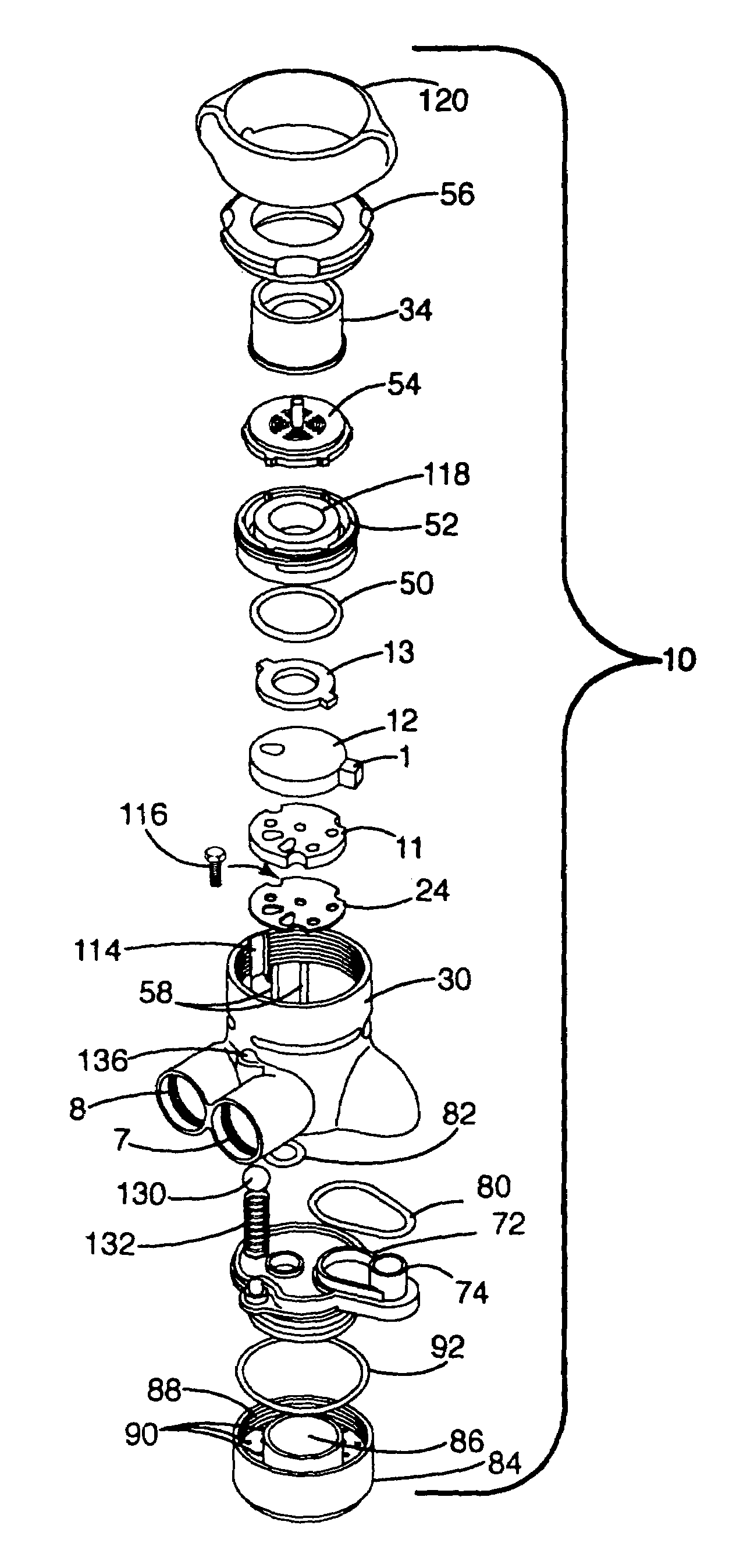
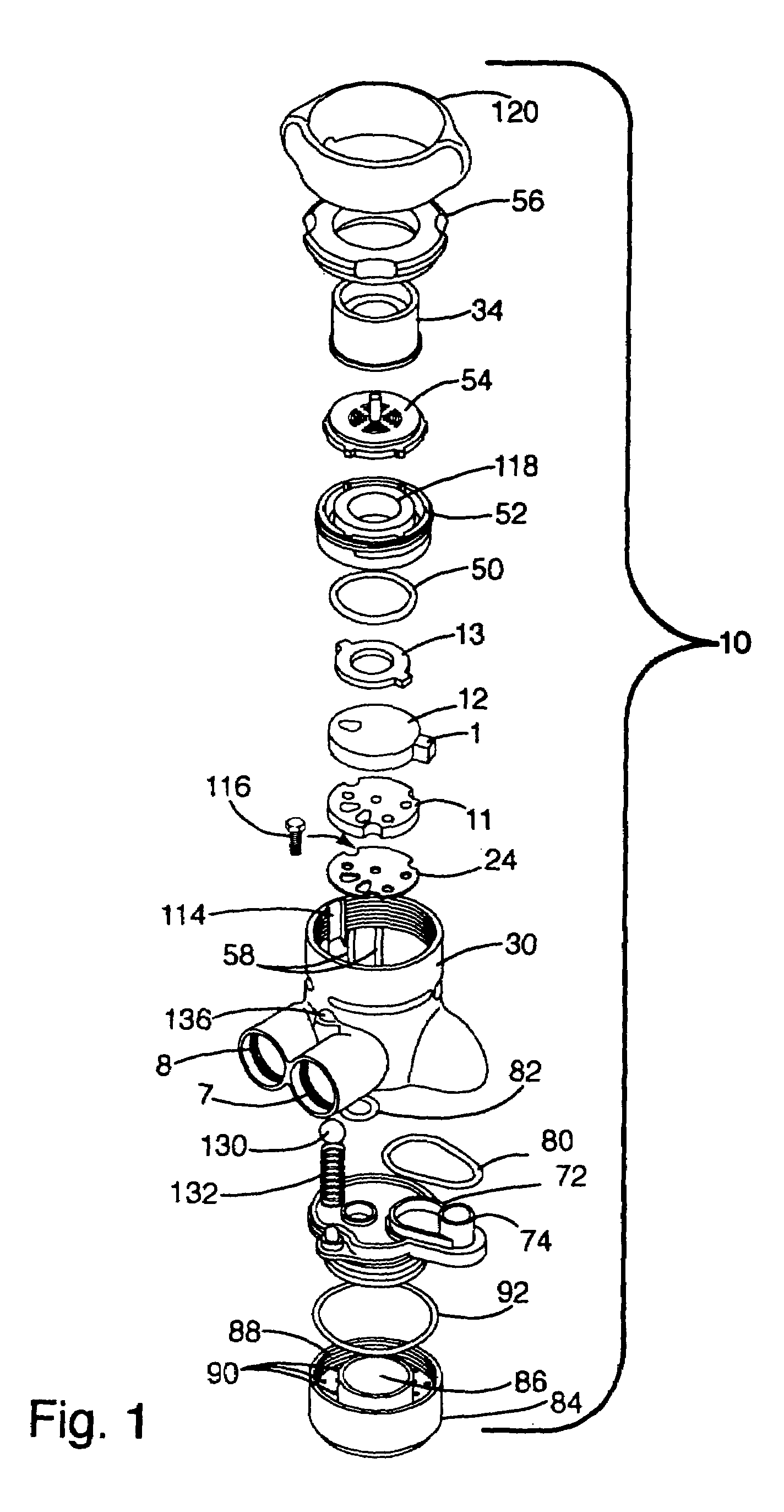
[0037]A ceramic disc diverter valve according to a preferred embodiment of the present invention is shown in FIG. 1, and is generally designated 10. The ceramic disc diverter valve 10 mounts to a conventional faucet and is connected with a water treatment device (not shown). The diverter 10 selectively operates in three different modes: (1) treated mode in which the diverter delivers a flow of treated water from a treated water outlet 14, (2) untreated stream mode in which untreated water is delivered in a stream from an untreated water stream outlet 6, and (3) untreated spray mode in which untreated water is delivered in a spray from an untreated water spray outlet 5. To connect with the water treatment device, the diverter 10 includes a secondary outlet 8 to supply untreated water to the water treatment device and a secondary inlet 7 to receive treated water from the water treatment device. The diverter 10 includes in its general organization a valve body 30 and a movable center d...


PUM

PropertyMeasurementUnit
pressureaaaaaaaaaa
rotationaaaaaaaaaa
sizeaaaaaaaaaa

Abstract

A ceramic disc diverter valve for use with a water treatment device. The diverter includes a movable disc sandwiched between two stationary discs. The movable disc is rotated between three different positions to deliver a stream of untreated water, a spray of untreated water or a flow of treated water. When delivering treated water, the diverter directs the flow of water out of a secondary outlet to a water treatment device. The treated water is returned to the diverter through a secondary inlet and is discharged from the diverter through a treated water outlet. When delivering untreated water, both the secondary inlet and the secondary outlet are sealed by the ceramic discs. The movable disc preferably includes an integral handle that protrudes from the housing.

Description

PRIORITY CLAIM[0001]This application claims priority from U.S. Provisional Application No. 60 / 244,245, filed Oct. 30, 2000, entitled “Ceramic Disc Diverter Valve” and U.S. Provisional Application No. 60 / 259,948, filed Jan. 5, 2001, entitled “Ceramic Disc Diverter Valve”.RELATED APPLICATIONS[0002]This application is a continuation-in-part of patent application Ser. No. 10 / 039,443, filed on Oct. 29, 2001 now U.S. Pat. No. 6,634,380.BACKGROUND OF THE INVENTION[0003]1. Field of the Invention[0004]The present invention relates to diverter valves and more particularly to a ceramic disc diverter valve for attachment to a water faucet to selectively control the flow of water through a water treatment system.[0005]2. Description of the Related Art[0006]The quality of water delivered through a faucet is a matter of concern to a great many people. For many people, the water furnished by municipal or building water supplies is sufficiently pure for washing or rinsing purposes, but not of suffic...

Claims


Application Information

Patent Timeline
Patent Type & Authority Patents(United States)
IPC IPC(8): F16K11/074F16K11/06
CPCF16K11/0743Y10T137/86863Y10T137/87249Y10T137/9464
Inventor BARTKUS, ERIC K.PIPPEL, BRADLEY J.
Owner ACCESS BUSINESS GRP INT LLC
Why Eureka
Try Eureka