Wheel bearing assembly

Inactive Publication Date: 2005-11-01
NTN CORP
View PDF35 Cites 9 Cited by
  • Summary
  • Abstract
  • Description
  • Claims
  • Application Information

AI Technical Summary

Benefits of technology

[0026]By concentrating the contact force between the wheel-mounting flange and the brake rotor when a wheel is tightened to the hub bolts at portions near the hub bolts, even if there are undulating components on the brake rotor-mounting surface of the wheel-mounting flange and the surface of the brake rotor that abuts the brake rotor-mounting surface, the undulating components will not become a factor in deformation of the brake rotor. Thus it is possible to suppress deformation of the brake rotor and also the run-out of the brake rotor.
[0027]Further, in order to suppress deformation of the brake rotor, the following means may be adopted.
[0028]When the hub bolts are pressed into the wheel-mounting flange, if swelling develops around the holes formed in the wheel-mounting flange, flatness of the brake rotor-mounting surface of the wheel-mounting flange worsens, thus constituting a factor in deformation of the brake rotor. Thus, the fitting interference between the hub bolts, which are formed with a knurled portion on their outer periphery, and the holes in the wheel-mounting flange into which the knurled portions of the hub bolts are pressed, is restricted to within a range of 0.1–0.4 mm to suppress swelling around the holes in the wheel-mounting flange, thereby improving flatness of t

Problems solved by technology

While the film is formed of a material softer than steel, too soft of a material such as ru

Method used


Image

  • Wheel bearing assembly
  • Wheel bearing assembly
  • Wheel bearing assembly

Examples


Example

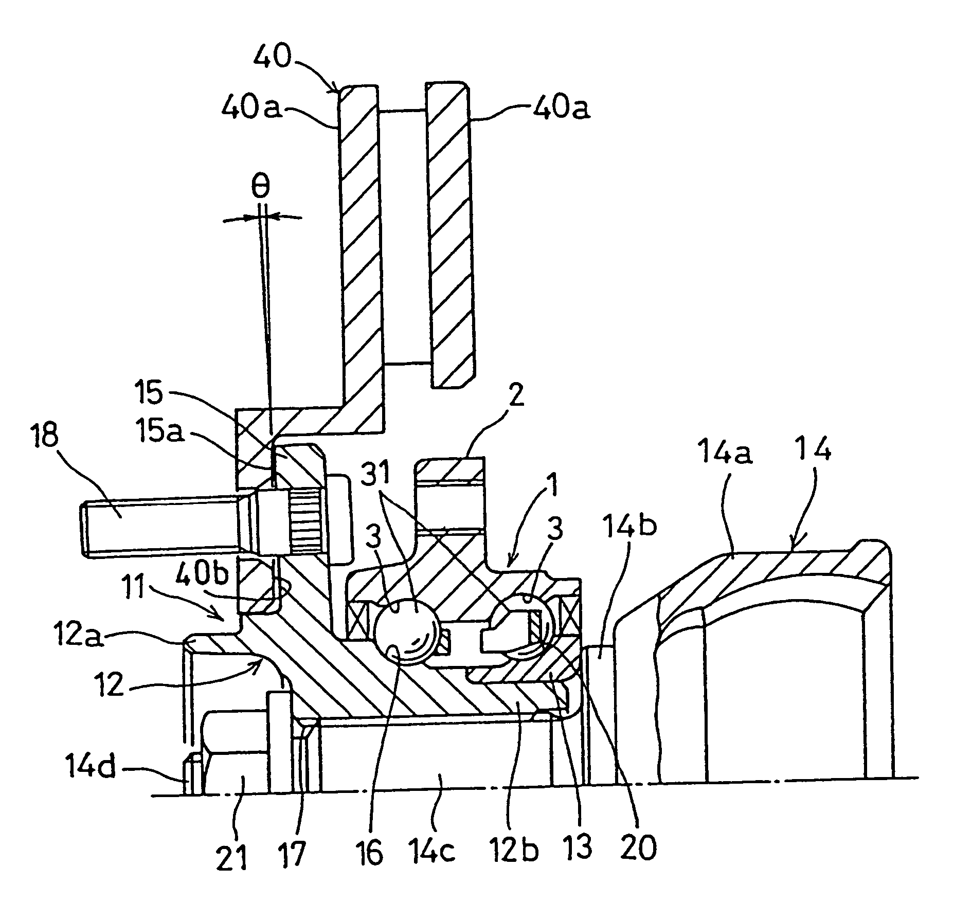
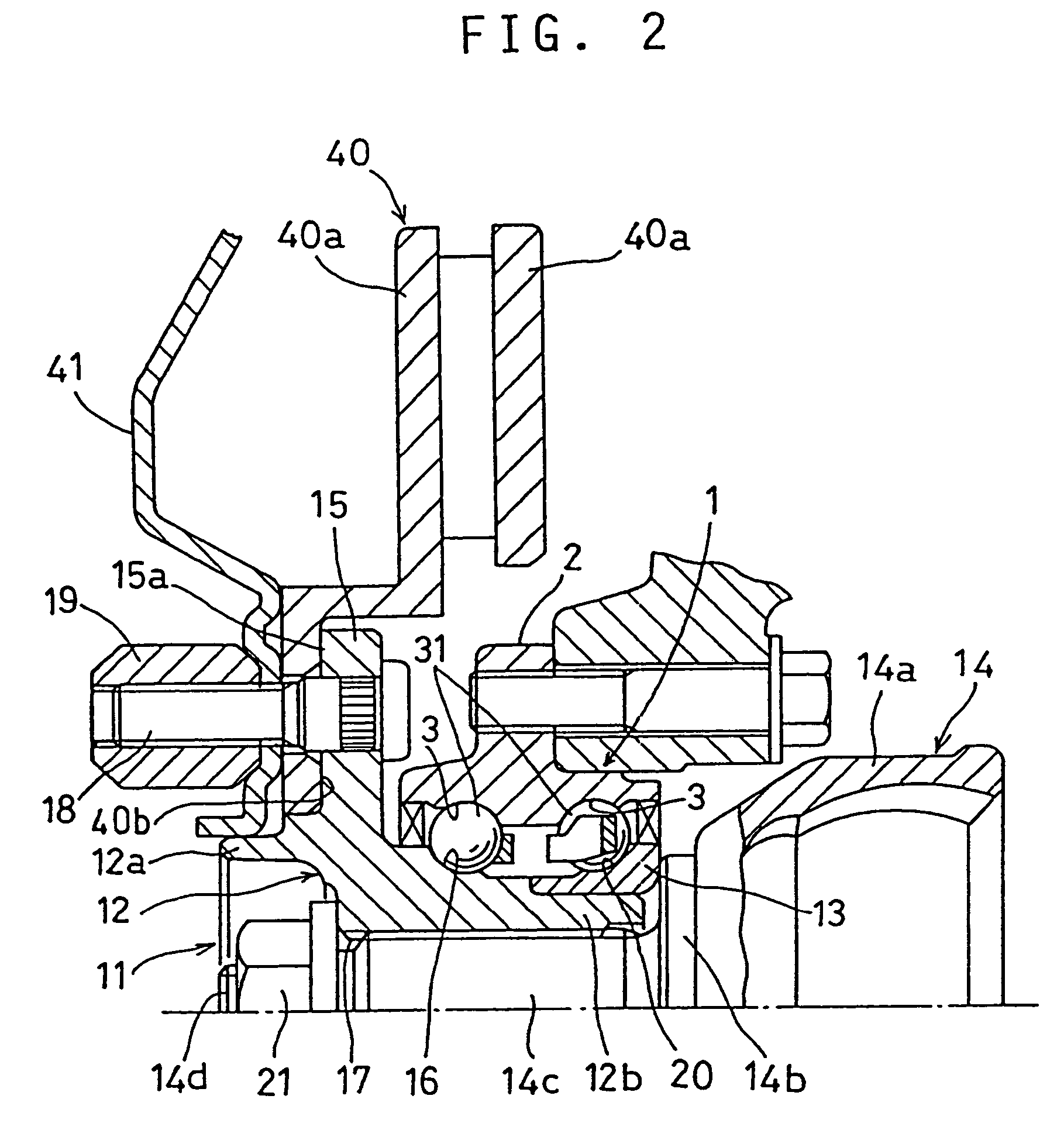
[0055]FIG. 1 shows a first embodiment which is a wheel bearing assembly for a driving wheel. This wheel bearing assembly comprises an outer member 1, an inner member 11 and rolling elements 31 mounted between the two members.

[0056]The outer member 1 has a mounting flange 2 for mounting to a vehicle body on its outer periphery and is formed with double-row raceways 3 on its inner periphery.

[0057]The inner member 11 comprises a hub ring 12, a raceway member 13 and an outer joint member 14 of a constant-velocity joint. A wheel pilot 12a is provided at one end of the hub ring 12, and at the other end, a small-diameter portion 12b is formed. Also on the outer periphery of the hub ring 12, a wheel-mounting flange 15 for mounting a wheel and a single-row raceway 16 are provided. Further, a spline hole 17 is formed in the hub ring 12.

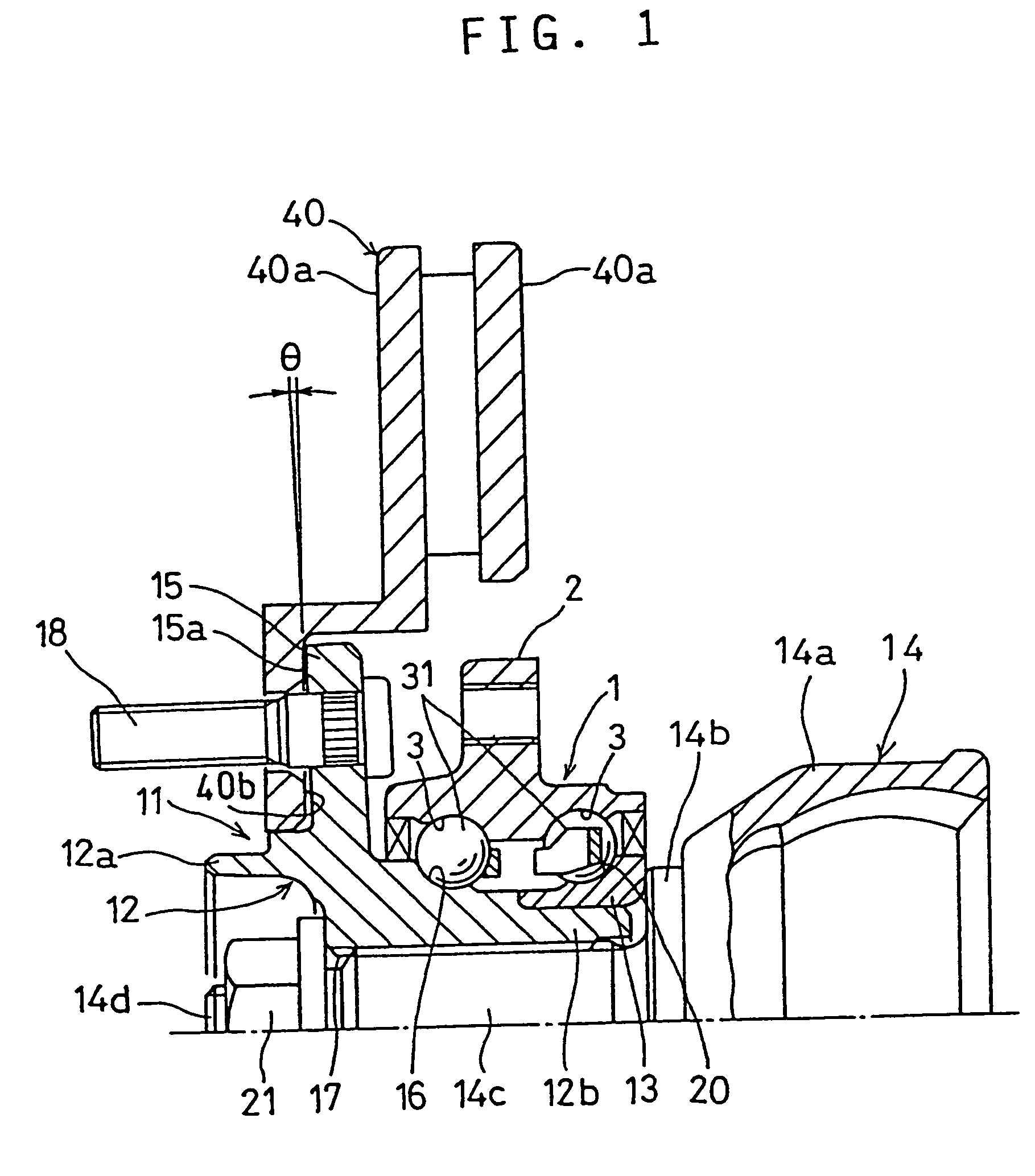
[0058]To the wheel-mounting flange 15, hub bolts 18 are mounted. Wheel nuts 19 are threadedly engaged with the hub bolts 18 as shown in FIG. 2. By tightening t...

Example

[0068]FIG. 5 shows a second embodiment which is a wheel bearing assembly for a driving wheel. It comprises an outer member 1, an inner member 11 and rolling elements 31 mounted between the two members.

[0069]The second embodiment is basically the same in structure as the first embodiment. Therefore the same numerals are used for the same or similar parts and detailed description is omitted.

[0070]In the wheel bearing assembly shown in FIG. 5, by concentrating the contact force between the wheel-mounting flange 15 and the brake rotor 40 when the disc wheel 41 of the wheel is tightened to the hub bolts 18, to portions near the hub bolts 18, the contact will be small on the surfaces between the adjacent hub bolts 18. Thus undulation of the surfaces between the adjacent hub bolts 18 will not become a factor for deformation of the brake rotor 40.

[0071]As a means for concentrating the contact force between the wheel-mounting flange 15 and the brake rotor 40 to portions near the hub bolts 18...

Example

[0084]FIG. 8 shows a third embodiment which is a wheel bearing assembly for a driving wheel. This wheel bearing assembly differs from the wheel bearing assembly shown in FIG. 1 only in the structure of the inner member. Thus, for the same parts, the same symbols are affixed and description is omitted.

[0085]The inner member 11 comprises a hub ring 51 and an outer joint member 52 of a constant-velocity joint. On the outer periphery of the hub ring 51, a wheel-mounting flange 53 and a raceway 54 are formed. In the hub ring 51, a spline hole 55 is formed.

[0086]The outer joint member 52 is provided with a spline shaft 52b at a closed end of a mouth portion 52a. On the outer peripheral surface of a shoulder portion 52c of the mouth portion 52a, a raceway 56 is formed. The spline shaft 52b is inserted in the spline hole 55 of the hub ring 51.

[0087]Rolling elements 31 are mounted between the raceway 54 formed on the hub ring 51 and one raceway 3 on the outer member 1 and between the raceway...


PUM


Abstract

A wheel bearing assembly is provided which can suppress brake judder. A film is disposed between the brake rotor-mounting surface of the wheel mounting flange and an abutment surface of a brake rotor to fill a gap therebetween to suppress the deformation of the brake rotor. Also, by concentrating the contact force between the wheel-mounting flange and the brake rotor when a disc wheel of the wheel is tightened to the hub bolts to a portion near the hub bolts, the contact between the wheel-mounting flange and the brake rotor on the surfaces between the hub bolts is suppressed so that undulation of the flat surfaces between the hub bolts will not cause deformation of the brake rotor.

Description

[0001]This application is a divisional application of application Ser. No. 09 / 897,459, filed Jul. 3, 2001 now U.S. Pat. No. 6,666,303.BACKGROUND OF THE INVENTION[0002]This invention relates to a wheel bearing assembly for supporting a vehicle wheel.[0003]Among vehicle wheel bearing assemblies, there are ones for supporting driving wheels and ones for supporting non-driving wheels. Among both types of wheel bearing assemblies, there are many types.[0004]FIG. 13 shows one example thereof. This wheel bearing assembly is for a driving wheel, and comprises an outer member 1, an inner member 11 and double-row rolling elements 31 mounted between the outer member 1 and the inner member 11.[0005]On the inner periphery of the outer member 1, two raceways 3 are formed while on the outer periphery thereof, a flange 2 for mounting to the vehicle body is provided.[0006]The inner member 11 has a hub ring 12 and a raceway member 13. A wheel-mounting flange 15 is provided on the outer periphery of t...

Claims


Application Information

Patent Timeline
IPC IPC(8): B60B27/00F16D65/12F16D65/00
CPCB60B27/00F16D65/0006F16D65/12F16D2065/1384F16D2250/0084
Inventor TORII, AKIRAFUKUSHIMA, SHIGEAKITAJIMA, EIJI
Owner NTN CORP
Why Eureka
Try Eureka