Inventory control and identification method

a control system and inventory technology, applied in the field of inventory identification and control systems, can solve the problems that prior art does not teach a smart label with two-way radio communication capability for use in a three-space locating system, and achieve the effects of reducing the cycle time of stocking process, reducing the setup time of new stores, and improving stocking problems

Inactive Publication Date: 2005-11-01
NEUMARK YORAM
View PDF21 Cites 113 Cited by
  • Summary
  • Abstract
  • Description
  • Claims
  • Application Information

AI Technical Summary

Benefits of technology

[0021]The primary purpose of the present invention is to incorporate the information displayed in such an electronic labeling system with the ability to determine the accurate location of each label and to provide an interactive data storage capability, that includes not only the data displayed by the label but also its location. This enables a virtual map of a storage facility such as a retail store and provides significant advantages. A further purpose of the present invention is to identify the quantity of each item in storage upon interrogation.
[0022]Such a system reduces the stocking process cycle time, cuts down on new store setup-time, improves stocking issues such as over or under stocking, and enables users to locate a specific stock item quickly. For on line shoppers, or from a store kiosk, locating items is very easy.
[0023]Transceivers are matched to labels and attached to shelves to identify specific stock items. The transceivers communicate so as to determine current location, as described in the prior art. Each label displays information pertaining to a specific stock item. Communication with the computer system to update the database with current location is easily accomplished. Such updates can be performed on a regular schedule, when a unit detects a change in its location or per user request when trying to locate a specific item.
[0024]All physical fixtures, i.e. shelves, hooks, displays etc. are mapped as to exact size and location in the database. This results in the ability to create a “virtual” store layout.

Problems solved by technology

However, the prior art does not teach a smart label with two-way radio communication capability for use in a three-space locating system.

Method used


Image

  • Inventory control and identification method
  • Inventory control and identification method
  • Inventory control and identification method

Examples


Embodiment Construction

[0037]The above described drawing figures illustrate the invention in at least one of its preferred embodiments, which is further defined in detail in the following description.

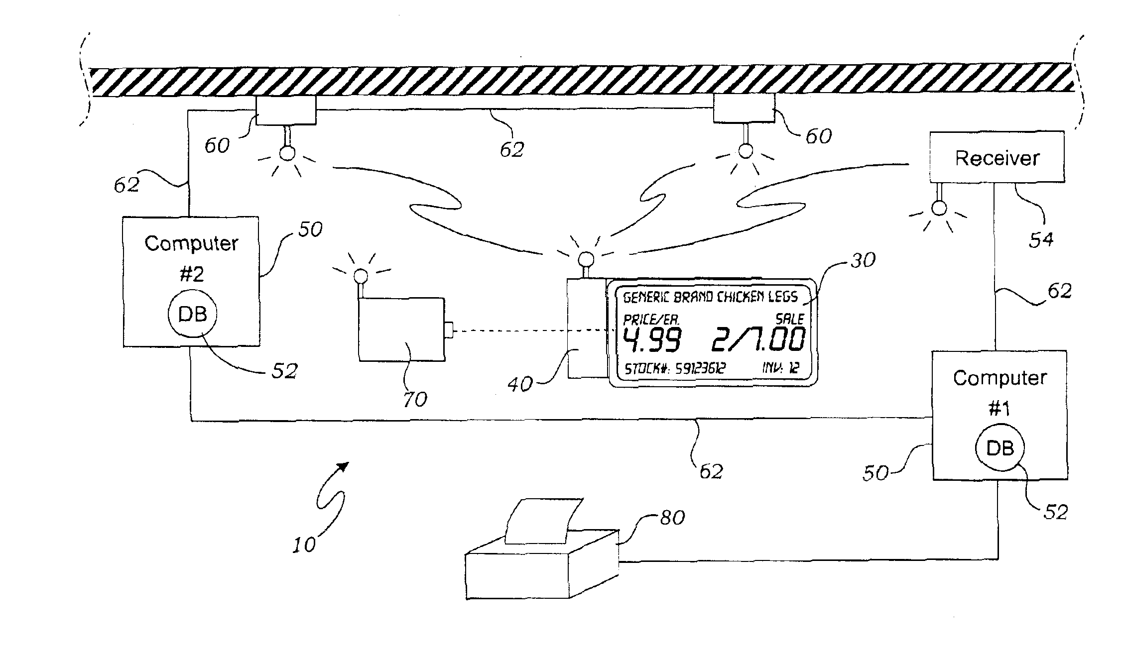
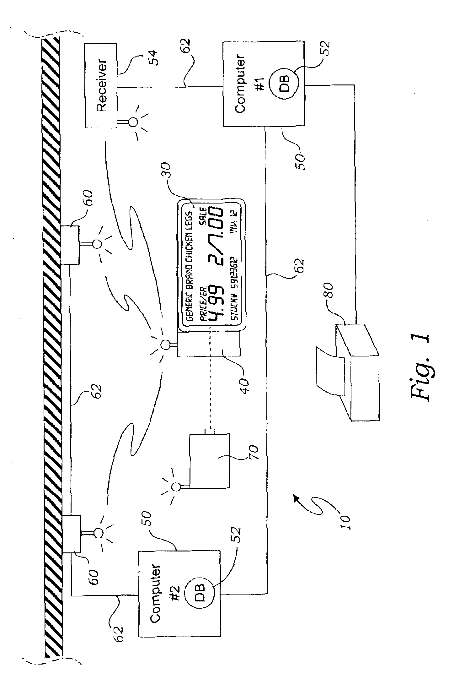
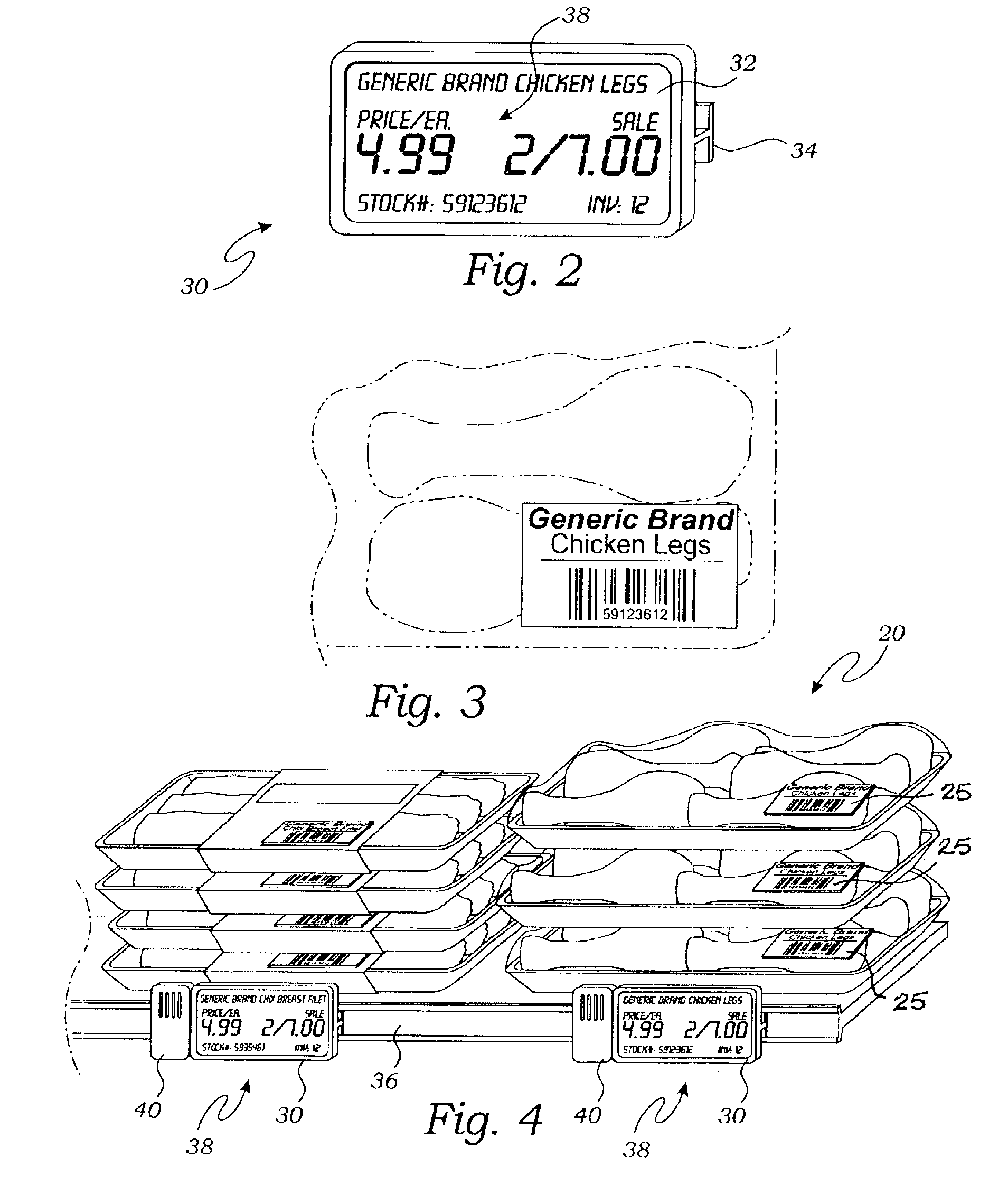
[0038]The present invention is a system and method for the identification of inventory stocks wherein the location and identity of any stock may be determined and its identity tag changed; all from a remote location. The system is also able to determine how much inventory is held at each location, shelf or bin, and transmit such information to data storage. The system uses a storage space 10, such as a warehouse, a supermarket, a parking garage, and a dead storage facility, and may be plural storage spaces 10 within a building, for instance, such as on different floors, or may even be in separate facilities. The storage space 10 receives a plurality of inventory items 20 (stock) such as packages, food containers, vehicles and discarded obsolete equipments; and may be any other type of item or item groups that...


PUM


Abstract

An inventory control and identification apparatus uses a storage space with a plurality of inventory items. Identification labels are positioned in physical correspondence with the inventory items. Each of the identification labels provides a transceiver. A coordinate communications network of further transceivers is set in a fixed position relative to the storage space and is enabled for wireless communication with the identification labels. A data processor is enabled for wireless communication with the coordinate network and the identification labels so as to receive data from the labels and the network. Inventory items have RF ID tags. Interrogation by the labels enables the tags to emit codes identifying the presence and location of the inventory to the labels. Triangulation of signals transmitted by the labels enables location of the labels in three-space.

Description

RELATED APPLICATIONS[0001]This is a continuation-in-part application of a prior filed and currently pending application having Ser. No. 10 / 304,671 and file date of Nov. 25, 2002 now U.S. Pat. No. 6,736,316.INCORPORATION BY REFERENCE[0002]Applicant(s) hereby incorporate herein by reference, any and all U.S. patents, U.S. patent applications, and other documents and printed matter cited or referred to in this application.BACKGROUND OF THE INVENTION[0003]1. Field of the Invention[0004]This invention relates generally to inventory identification and control systems and more particularly to a system using inventory identity labels mounted adjacent to inventory items, the labels providing identification information relative to the inventory and wherein the labels are enabled for communication with tags on the inventory items and with a computerized inventory management system, and wherein the inventory location, quantity and status is known at any time from a remote location.[0005]2. Desc...

Claims


Application Information

Patent Timeline
Patent Type & Authority Patents(United States)
IPC IPC(8): G06K17/00
CPCG06K17/0022G06Q10/087G06K2017/0051G06K2017/0093
Inventor NEUMARK, YORAM
Owner NEUMARK YORAM
Why Eureka
Try Eureka