
Humidity controller

a humidity controller and humidity control technology, applied in domestic cooling devices, heating types, separation processes, etc., can solve the problems of insufficient reduction of relative humidity of room air introduced into the adsorbing rotor after heating, inability to secure an amount of moisture (i.e., an amount of humidification) desorbed from the adsorbent, and inability to achieve sufficient humidification performance, etc., to suppress an increase in the first air temperature, the effect of high efficiency of the humidity control

Inactive Publication Date: 2005-11-01
DAIKIN IND LTD
View PDF12 Cites 32 Cited by
  • Summary
  • Abstract
  • Description
  • Claims
  • Application Information

AI Technical Summary

Benefits of technology

[0042]In the invention, the second air sent to the adsorbing elements (81, 82, . . . ) for regenerating the adsorbent is the mixture of the room air and the outside air. Here, if only one of the room air and the outside air is used as the second air, the temperature and the humidity of the second air are uniquely determined by a state of the room air or the outside air. On the other hand, according to the invention, the mixture of the room air and the outside air is used as the second air. Consequently, the temperature and the humidity of the second air can be changed if necessary. Therefore, according to the invention, by appropriately setting a state of the second air, it is possible to keep efficiency of the humidity control apparatus high and to ensure sufficient performance of humidification.
[0043]In the second means to solve the problem, the cooling-side passage (86) is formed in the adsorbing elements (81, 82, . . . ) to cause the cooling fluid to absorb the heat of adsorption generated in the adsorbing operation. Therefore, according to the present means to solve the problem, it is possible to suppress an increase in a temperature of the first air due to the generated heat of adsorption. As a result, a relative humidity of the first air flowing through the humidity-control-side passage (85) of the adsorbing elements (81, 82, . . . ) can be maintained at a high value and an amount of water vapor adsorbed by the adsorbent can be increased.
[0044]In the third means to solve the problem, the second air is first introduced into the cooling-side passage (86) of the adsorbing elements (81, 82, . . . ) as the cooling fluid and the second air flowing out of the cooling-side passage (86) is heated by the heater (92). In other words, the second air used for regeneration of the adsorbing elements (81, 82, . . . ) is heated not only in the heater (92) but also in the cooling-side passage (86) of the adsorbing elements (81, 82, . . . ). Therefore, according to the present means to solve the problem, an amount of heat which should be given to the second air by the heater (92) can be reduced and energy required for operation of the humidity control apparatus can be reduced.
[0045]In the twelfth means to solve the problem, the heating medium for cooling is introduced into the adsorbing elements (311, 312, . . . ) in the adsorbing operation to cause the heating medium to absorb the heat of adsorption generated in the adsorbing operation. Therefore, according to the present means to solve the problem, it is possible to suppress an increase in a temperature of the first air due to the generated heat of adsorption. As a result, a relative humidity of the first air passing through the adsorbing elements (311, 312, . . . ) can be maintained at a high value and an amount of water vapor adsorbed by the adsorbent can be increased.
[0046]Especially in the seventh to eleventh and thirteenth and fifteenth means to solve the problem, the mixture ratio between the room air and the outside air forming the second air is appropriately adjusted by using various parameters. Therefore, according to these means to solve the problem, a state of the second air used for regeneration of the adsorbent can be set further appropriately to thereby enhance efficiency and performance of humidification of the humidity control apparatus.

Problems solved by technology

However, there is a fear that sufficient humidifying performance cannot be obtained in the above humidity control apparatus.
Therefore, a relative humidity of the room air introduced into the adsorbing rotor after heating cannot be reduced sufficiently and there was a fear that an amount of moisture (i.e., an amount of humidification) desorbed from the adsorbent cannot be secured.
As a result, energy required for heating increases and efficiency of the humidity control apparatus is reduced.

Method used


Image

  • Humidity controller
  • Humidity controller
  • Humidity controller

Examples


embodiment 1

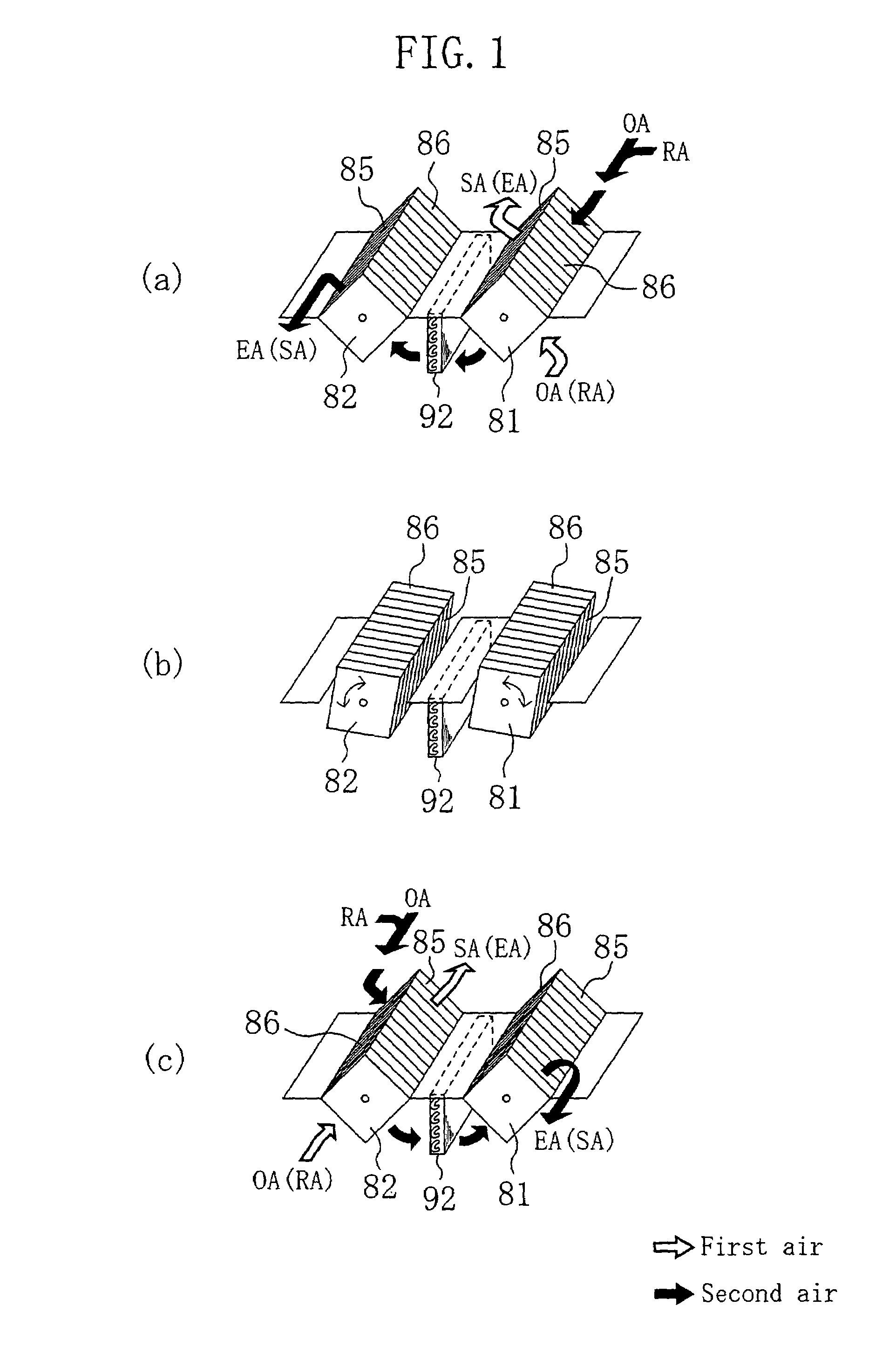
[0057]A humidity control apparatus is formed to carry out a dehumidifying operation for supplying dehumidified and cooled outside air into a room and a humidifying operation for supplying heated and humidified outside air into the room while switching between the operations. The humidity control apparatus includes two adsorbing elements (81, 82) and carries out an operation of a so-called batch type.

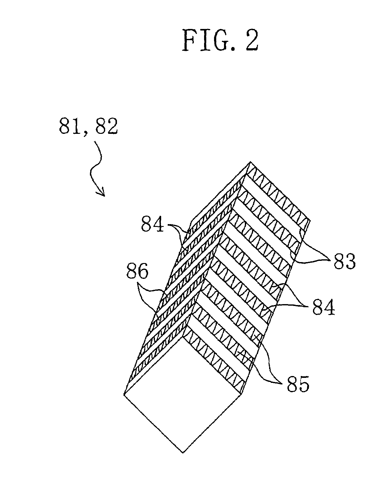
[0058]As shown in FIG. 1, the respective adsorbing elements (81, 82) are formed into shapes of square columns. Specific structures of the adsorbing elements (81, 82) will be described later. The two adsorbing elements (81, 82) are arranged on the left and right and housed in a casing outside the drawing.

[0059]To put it concretely, in the casing of the humidity control apparatus, the first adsorbing element (81) is disposed on the right side and the second adsorbing element (82) is disposed on the left side. These adsorbing elements (81, 82) are disposed such that their longitudinal dire...

embodiment 3

[0105]A humidity control apparatus according to the invention includes one adsorbing element (200). The humidity control apparatus takes in the first air and the second air and carries out a dehumidifying operation or a humidifying operation while alternately carrying out a first operation and a second operation.

[0106]As shown in FIG. 4, the adsorbing element (200) of the present embodiment is formed by alternately laminating rectangular flat plate members (83) and corrugated plate members (84). The adsorbing element (200) is formed similarly to that of the embodiment 1 except its entire shape.

[0107]To put it concretely, the adsorbing element (200) is formed in a shape of a rectangular parallelepiped which is long in a lateral direction and rather flat as a whole. In this adsorbing element (200), the flat plate members (83) and the corrugated plate members (84) are laminated in a longitudinal direction. Humidity-control-side passages (85) are open in front and back faces in FIG. 4 a...

fourth embodiment

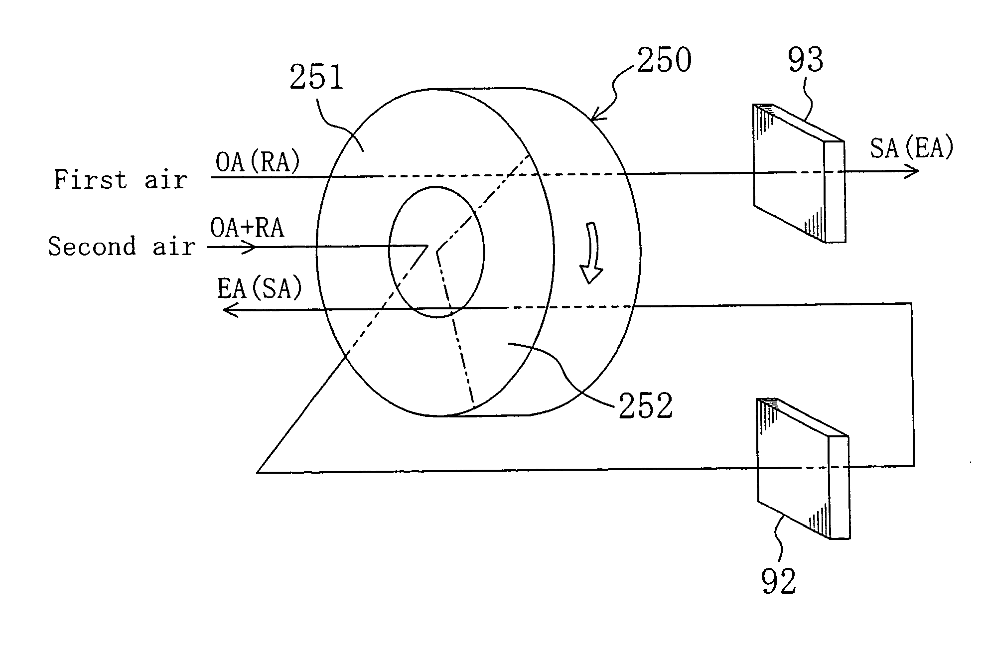
[0129]A humidity control apparatus according to the invention includes one adsorbing element (250). The humidity control apparatus takes in first air and second air and carries out an adsorbing operation and a regenerating operation with regard to one adsorbing element (250) in parallel with each other. In other words, in the humidity control apparatus of the present embodiment, dehumidification of air by the adsorbing element (250) and regeneration of adsorbent of the adsorbing element (250) are carried out simultaneously in parallel.

[0130]As shown in FIG. 6, the adsorbing element (250) of the embodiment is formed in a shape of a doughnut or a thick-walled cylinder. In the adsorbing element (250), humidity-control-side passages (85) and cooling-side passages (86) are defined alternately in a circumferential direction of the adsorbing element (250). The humidity-control-side passages (85) pass through the adsorbing element (250) in an axial direction of the adsorbing element (250). ...


PUM


Abstract

A humidity control apparatus is provided with two adsorbing elements. The humidity control apparatus alternately repeats a first operation for dehumidifying air in the first adsorbing element while regenerating the second adsorbing element and a second operation for dehumidifying air in the second adsorbing element while regenerating the first adsorbing element. The second air taken into the humidity control apparatus is formed of a mixture of room air and outside air. In the humidity control apparatus, a mixture ratio between the room air and the outside air in the second air is variable.

Description

TECHNICAL FIELD[0001]The present invention relates to a humidity control apparatus for controlling a humidity of air.BACKGROUND ART[0002]A humidity control apparatus for controlling a humidity of air by using an adsorbent is known conventionally. For example, a combination of a humidity control apparatus of this type and an air conditioner is disclosed in Japanese Patent Application Laid-open No. 8-128681.[0003]To put it concretely, the humidity control apparatus described in the above official gazette includes a disc-shaped absorbing rotor. The adsorbing rotor is disposed astride a flow path for room air and a flow path for outside air and is driven for rotation about its axis. In other words, a portion of the adsorbing rotor is in contact with the room air and the rest of the rotor is in contact with the outside air. The adsorbing rotor is provided with an adsorbent.[0004]In the humidity control apparatus, the outside air is supplied to the adsorbing rotor and moisture in the outs...

Claims


Application Information

Patent Timeline
Patent Type & Authority Patents(United States)
IPC IPC(8): F24F3/147F24F3/12B01D53/26F24F3/14
CPCF24F3/1411F24F3/1423F24F3/147F24F3/1429F24F2203/1016F24F2203/1032F24F2203/1048F24F2203/1052F24F2203/1056F24F2203/1068F24F2203/1088
Inventor YABU, TOMOHIROKIKUCHI, YOSHIMASA
Owner DAIKIN IND LTD
Learn More