Sanding block

a technology of sanding blocks and sandpaper, which is applied in the direction of metal-working equipment, grinding/polishing hand tools, seat surface grinding machines, etc., can solve the problems of inefficient use of sandpaper, difficult to keep the edges of sandpaper from becoming torn or crumpled during use, and achieves simple structure for pulling and maintaining, and the effect of reducing was

Inactive Publication Date: 2005-11-01
MICK JERRY
View PDF15 Cites 12 Cited by
  • Summary
  • Abstract
  • Description
  • Claims
  • Application Information

AI Technical Summary

Benefits of technology

[0011]A further object of the present invention is to provide a sanding block that can be used with standard size round sheets of sandpaper having loop-type material covering the back side thereof so the user does not have to cut sandpaper.
[0013]A further object of the present invention is to provide a sanding block that allows the entire sheet of sandpaper to be used with minimal waste, that includes a simple structure for pulling and maintaining the sandpaper taut across the bottom side of the sanding block, that allows the sandpaper to be changed quickly and easily, and that is economical to manufacture and easy to use.

Problems solved by technology

While these devices were adequate for some purposes, they required some means of holding the ends of the sandpaper while applying one face of the block against the surface being sanded.
This resulted in inefficient use of the sandpaper because the ends were generally never exposed to the surface being sanded.
However, when these self-adhering sandpapers are adhered directly to the working face of a sanding block, it is sometimes difficult to apply adequate pressure to the surface being sanded due to the cushion effect provided by the adhesive system, and it is also sometimes difficult to keep the edges of the sandpaper from becoming torn or crumpled during use.
However, once a piece of sandpaper with a pressure-sensitive coating is applied onto a block or sander, it cannot be readily changed until the sandpaper is ready to be disposed of because the sandpaper does not peel without tearing and will not re-stick.
This makes changing back and forth between different grits of sandpaper difficult and costly.

Method used


Image

  • Sanding block
  • Sanding block
  • Sanding block

Examples


Embodiment Construction

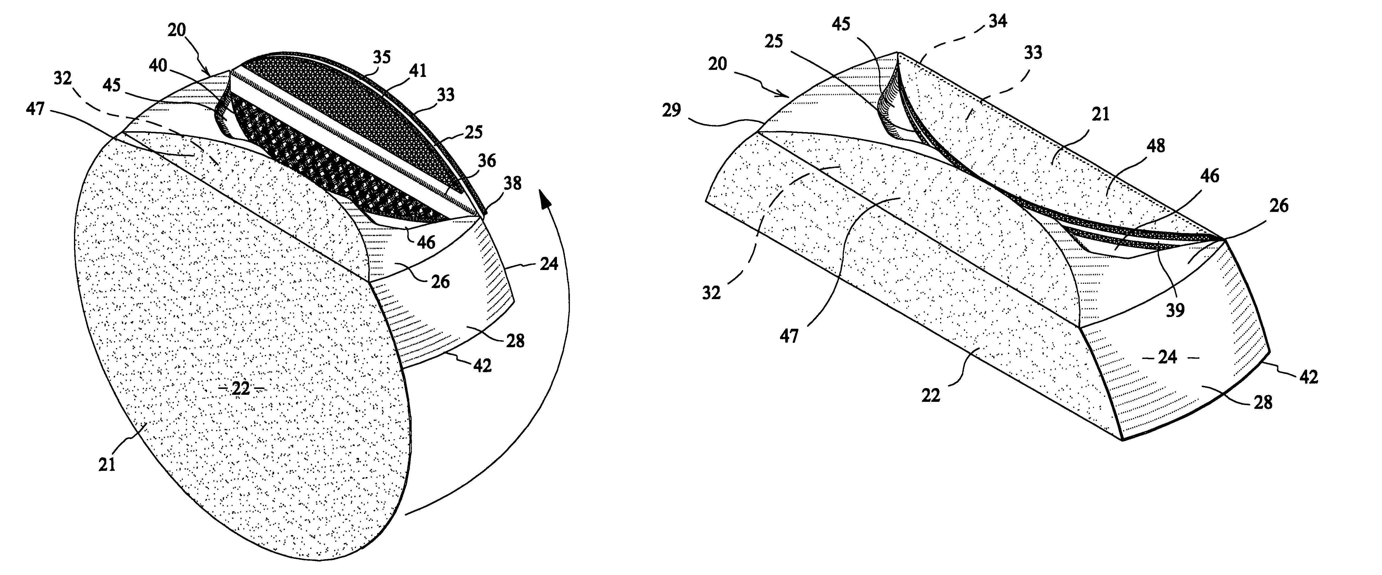
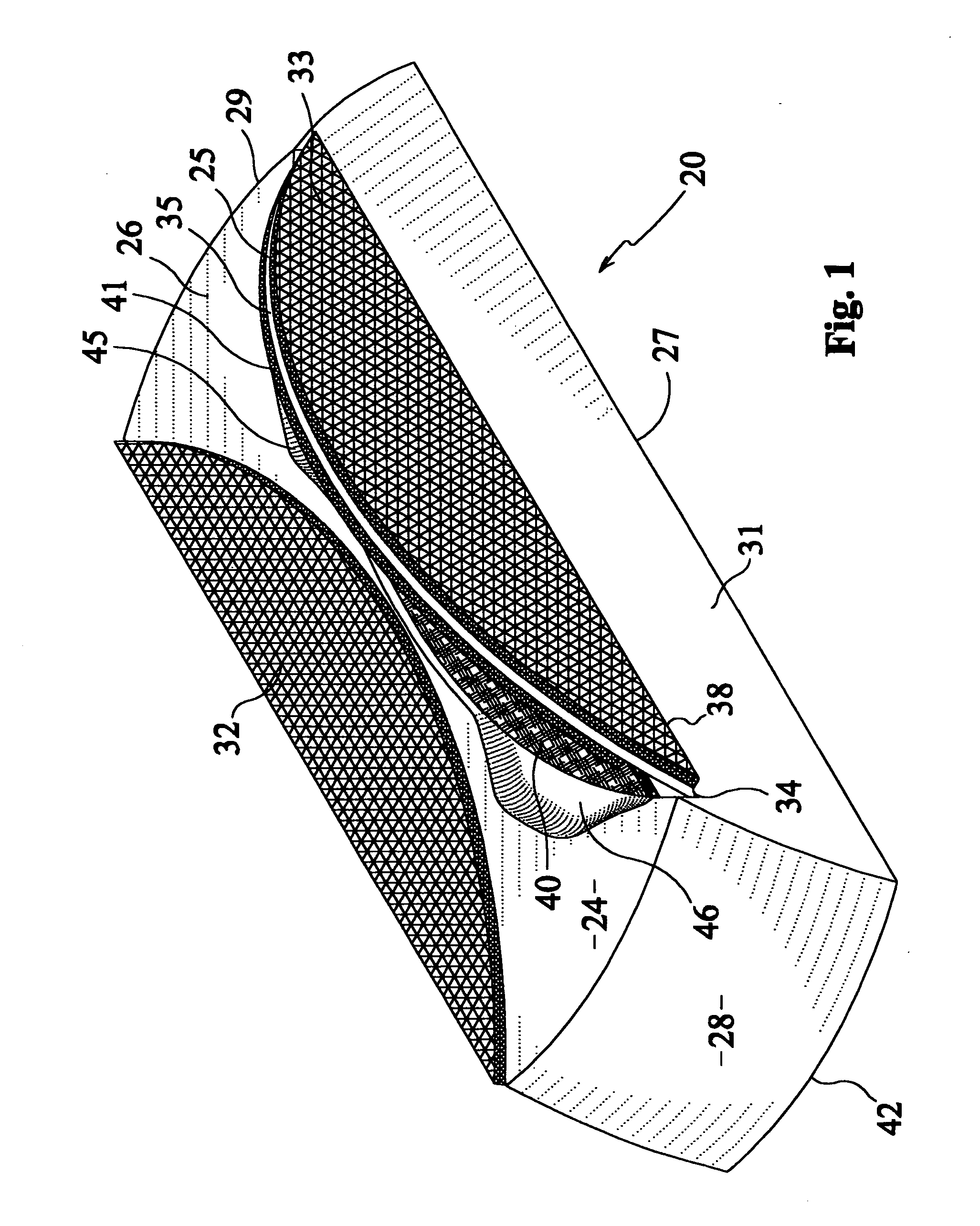
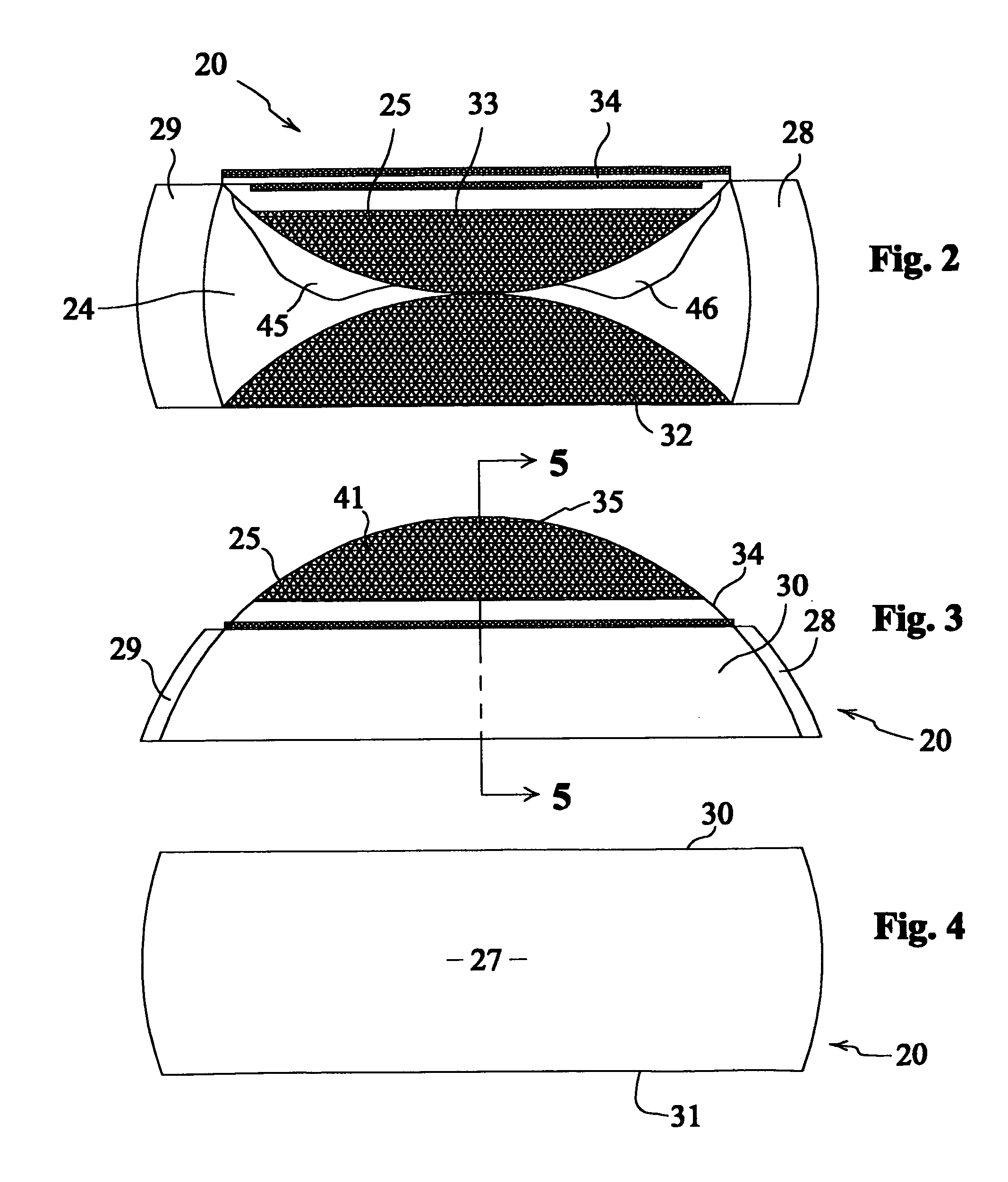
[0032]A sanding block 20 according to a preferred embodiment of the present invention will now be described with reference to FIGS. 1 to 14 of the accompanying drawings.

[0033]The sanding block 20 according to the present invention is made for hand held use with a conventional round sheet of sandpaper 21 having a first side covered by an abrasive material 22 and a second side covered by a first component 23 of a fastening system, such as a loop-type or hook-type fastening material. Such sandpaper 21 is commercially available, for example, from the 3M Company under the proprietary names, “Hook-It” and “Hook-It II” sandpaper, and is generically referred to in this application as non-holed hook and loop-type sandpaper. In the preferred embodiment, a six-inch (6″) diameter sheet of sandpaper 21 is used. Other sizes of sandpaper 21 can be used to suit a particular application without departing from the present invention.

[0034]The sanding block 20 has a main body 24 and a flap member 25 se...


PUM


Abstract

A sanding block for hand held use has a main body with a bottom side providing a surface for pressing a portion of a circular sheet of sandpaper against an article to be sanded. A first hook and loop-type fastener is secured to the top side of the main body for coupling with a corresponding material covering a backside of the sandpaper. A flap member is secured to the main body and is swingable between first and second positions. A second hook and loop-type fastener is secured to the flap member for coupling with the material covering the backside of the sandpaper. The flap member and the second fastener are arranged to pull the sheet of sandpaper taut across the bottom side when the flap member is moved from its first position to its second position. A closure system is provided for holding the flap member in its second position.

Description

BACKGROUND OF THE INVENTION[0001]1. Field of the Invention[0002]The present invention relates generally to sanding devices. More particularly, the present invention relates to improvements in sanding blocks.[0003]2. Description of the Related Art[0004]Woodworking projects typically involve sanding of the wood before a finish is applied to the wood. Other surfaces, such as drywall and automotive bodies, are also commonly sanded before a finish is applied. Such sanding has been aided by use of power sanding devices, but almost invariably, some amount of hand sanding is generally needed in any quality sanding job.[0005]Hand sanding has been performed using a variety of sanding blocks, sanding sticks, sanding pads, and individual pieces of sandpaper. The sanding process often must be carried out using multiple grades of abrasive to achieve a quality smooth surface that is free of sanding marks.[0006]Early sanding blocks were simply blocks of solid material, such as wood, over which rect...

Claims


Application Information

Patent Timeline
Patent Type & Authority Patents(United States)
IPC IPC(8): B24D15/00B24D15/02
CPCB24D15/023
Inventor MICK, JERRY
Owner MICK JERRY
Why Eureka
Try Eureka