Laminated cross lumber and method of making same

a cross-leaf, laminated technology, applied in the direction of lamination auxiliary operations, lamination apparatus, stapling tools, etc., can solve the problems of difficult reuse, difficult to obtain wood members of dimensions and quality, and large available sizes

Inactive Publication Date: 2005-11-01
PINEXEL
View PDF12 Cites 15 Cited by
  • Summary
  • Abstract
  • Description
  • Claims
  • Application Information

AI Technical Summary

Benefits of technology

[0010]It is therefore an aim of the present invention to provide a method for making a laminated cross lumber beam that is simple.
[0011]It is another aim of the present invention to provide a method for making a laminated cross lumber beam that can be further simplified by the use of small wood members.
[0012]It yet another aim of the present invention to provide a method for making a laminated cross lumber beam that easily integrates the use of wood members containing flash.
[0013]It is an additional aim of the present invention to provide a method for making a laminated cross lumber beam that easily integrates the use of wood members of non standard dimensions.
[0014]It is a further aim of the present invention to provide a method for making a laminated cross lumber beam that produces a beam of superior mechanical properties and pleasing visual appearance.

Problems solved by technology

Unfortunately, the fabrication of traditional laminated beams requires the use of wood members of dimensions and quality that have become increasingly harder to obtain due to the fact that nowadays the trees available are a lot smaller than they once were.
Also, the cutting of wood for various elements required in construction work generates a great quantity of pieces of small dimensions, difficult to reuse thus usually considered as waste.
This high proportion of wasted material greatly increases fabrication costs.
While this configuration allows for the recycling of timbers of small length by joining them end to end through a pencil joint, it does not allow the use of timbers of varying thicknesses.
Moreover, defects such as flash must be removed before assembling the timbers, thereby reducing the proportion of waste material that can be reused.
However, this additional strip greatly increases the time and costs of manufacturing by augmenting the number of steps in the process.

Method used


Image

  • Laminated cross lumber and method of making same
  • Laminated cross lumber and method of making same
  • Laminated cross lumber and method of making same

Examples


Embodiment Construction

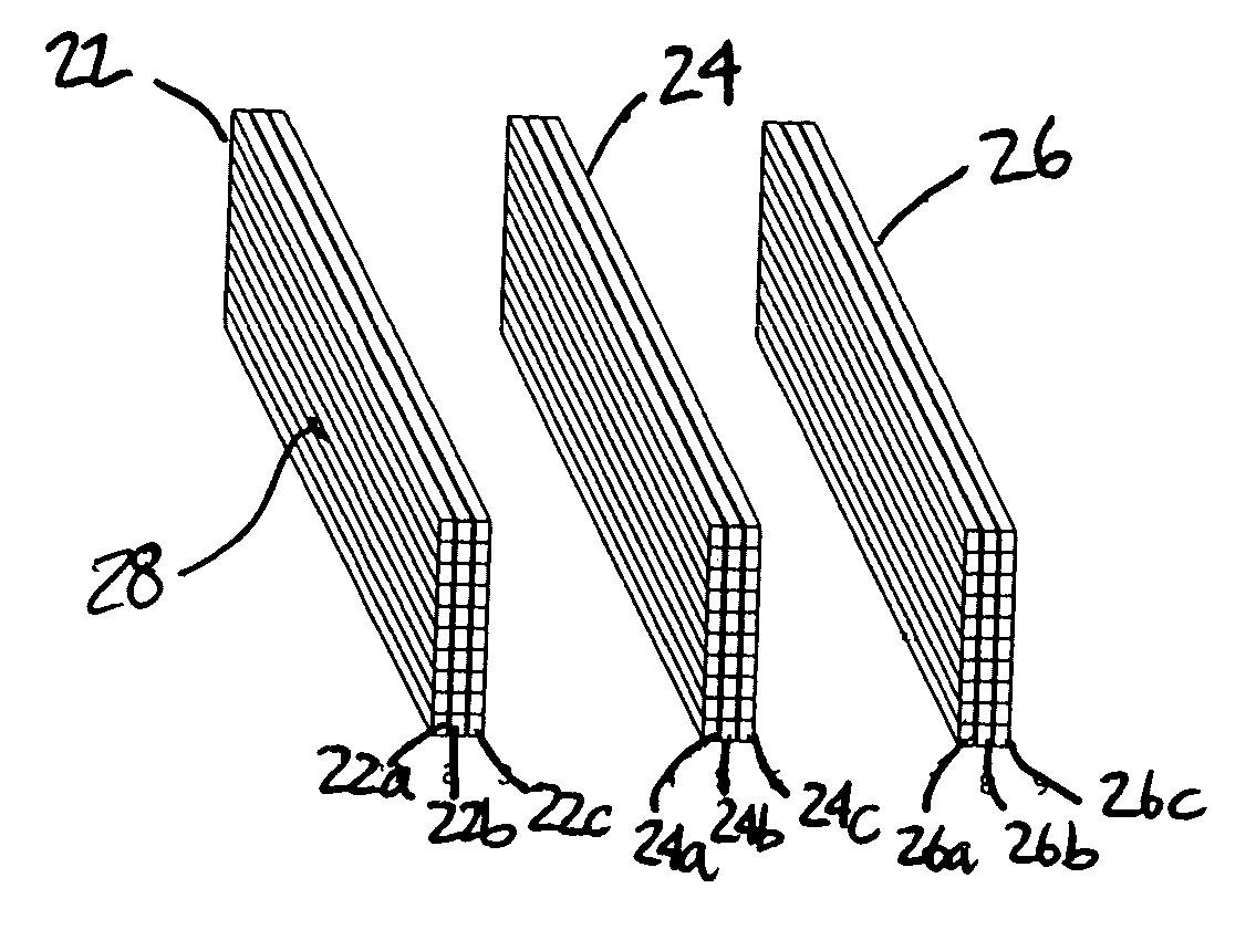
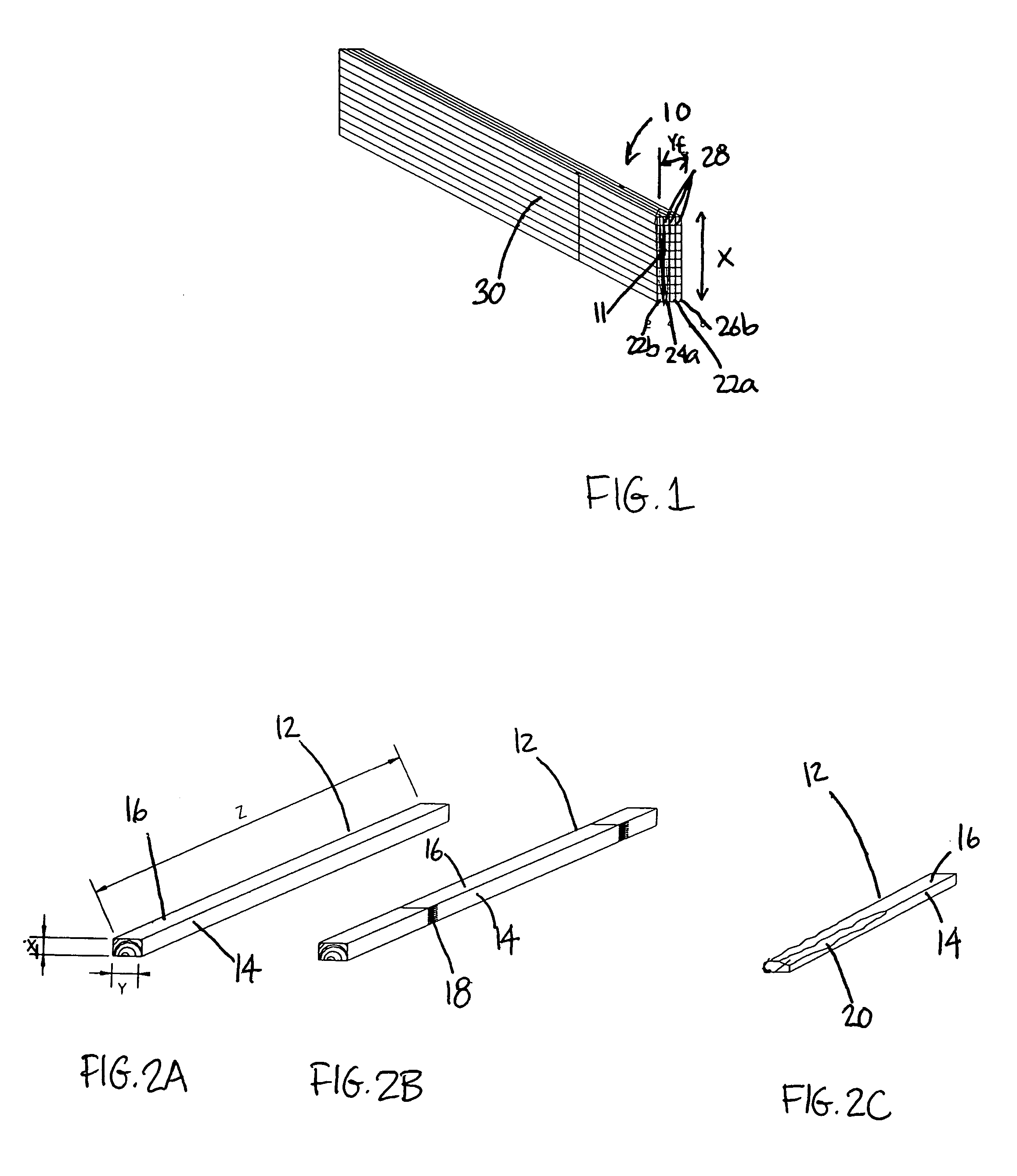
[0031]Referring now to FIG. 1, a laminated cross lumber beam or timber 10 is composed of a plurality of elongated wood pieces 11 bonded together face to face and side to side. This laminated cross lumber beam 10 presents the advantages of superior mechanical and physical properties and a visual aspect similar to a standard laminated beam, while being produced using a simple method that can be further simplified by the use of small wood members as a starting material. The simplicity of the process minimizes fabrication costs. The method used to produce this laminated cross lumber beam is described in the following.

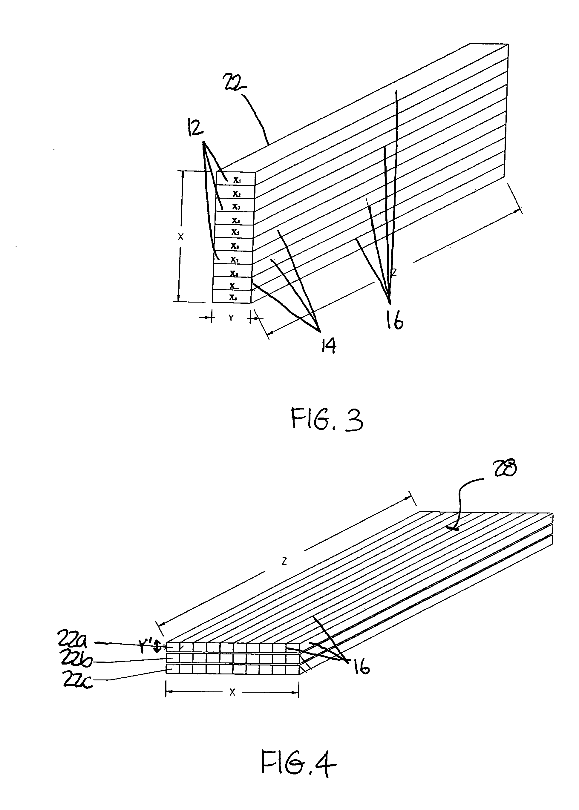
[0032]The starting material for the method according to the present invention is a plurality of elongated wood members 12. The wood members 12 include two longitudinal sides 14 and top and bottom wider longitudinal faces 16. Shown in FIG. 2 are different examples of wood members 12 that can be used: integral members (FIG. 2A), smaller members joined end to end through finge...


PUM

PropertyMeasurementUnit
humidityaaaaaaaaaa
humidityaaaaaaaaaa
lengthaaaaaaaaaa

Abstract

A method for making a laminated cross lumber beam comprising the step of stacking elongated wood members and bonding adjacent longitudinal faces thereof along a bonding plane to form intermediary beams. The method further includes a step of selecting intermediary beams having a width greater than a predetermined value and cutting them lengthwise perpendicularly to the bonding planes such as to form panels. The panels and uncut intermediary beams then form sub-beam elements. The method also includes a step of bonding at least two sub-beam elements together side by side to form the laminated cross lumber beam. This method is simplified by the use of small wood members which eliminates the need to cut the intermediary beam to form the sub-beam element. It requires a minimum of steps, thus minimizing costs. The product of this method is a beam with optimized mechanical properties and visual appearance.

Description

BACKGROUND OF THE INVENTION[0001]1. Field of the Invention[0002]The present invention relates to static wood structures. More particularly, the present invention relates to a method for making a laminated wood product.[0003]2. Background Art[0004]A variety of laminated wood beams are used in construction work today as joists, girders, posts, columns or other structural pieces. Laminated wood beams are known to be stronger, more resistant and more dimensionally stable than continuous wood beams. Unfortunately, the fabrication of traditional laminated beams requires the use of wood members of dimensions and quality that have become increasingly harder to obtain due to the fact that nowadays the trees available are a lot smaller than they once were. Thus, the wood members are often cut from trees of relatively small diameter, such as trees from plantation or northern forests, thereby producing members of low grade, small dimensions and with a high proportion of flash.[0005]Also, the cu...

Claims


Application Information

Patent Timeline
Patent Type & Authority Patents(United States)
IPC IPC(8): B27M3/00B27M1/00B27M1/08
CPCB27M1/08B27M3/0053B27M3/006Y10T156/1059Y10T156/1075
Inventor BRUNET, ALAIN
Owner PINEXEL
Why Eureka
Try Eureka