Switching gas damper for low-voltage power circuit breakers

a low-voltage power circuit and gas damper technology, which is applied in the direction of circuit-breaking switch details, air-breaking switches, high-tension/heavy-dress switches, etc., can solve the problems of not achieving the object and not representing any improvement of power circuit breakers, and achieve the effect of deflection of switching gas flows

Inactive Publication Date: 2005-11-01
SIEMENS AG
View PDF18 Cites 20 Cited by
  • Summary
  • Abstract
  • Description
  • Claims
  • Application Information

AI Technical Summary

Benefits of technology

[0020]The deflection of the switching gas flows can also be produced by the cover of the switching gas damper being designed to be broader than the low-voltage power circuit breaker and by providing side boundari

Problems solved by technology

This does not represent any improvement for power circuit breakers which have a

Method used


Image

  • Switching gas damper for low-voltage power circuit breakers
  • Switching gas damper for low-voltage power circuit breakers
  • Switching gas damper for low-voltage power circuit breakers

Examples


second embodiment

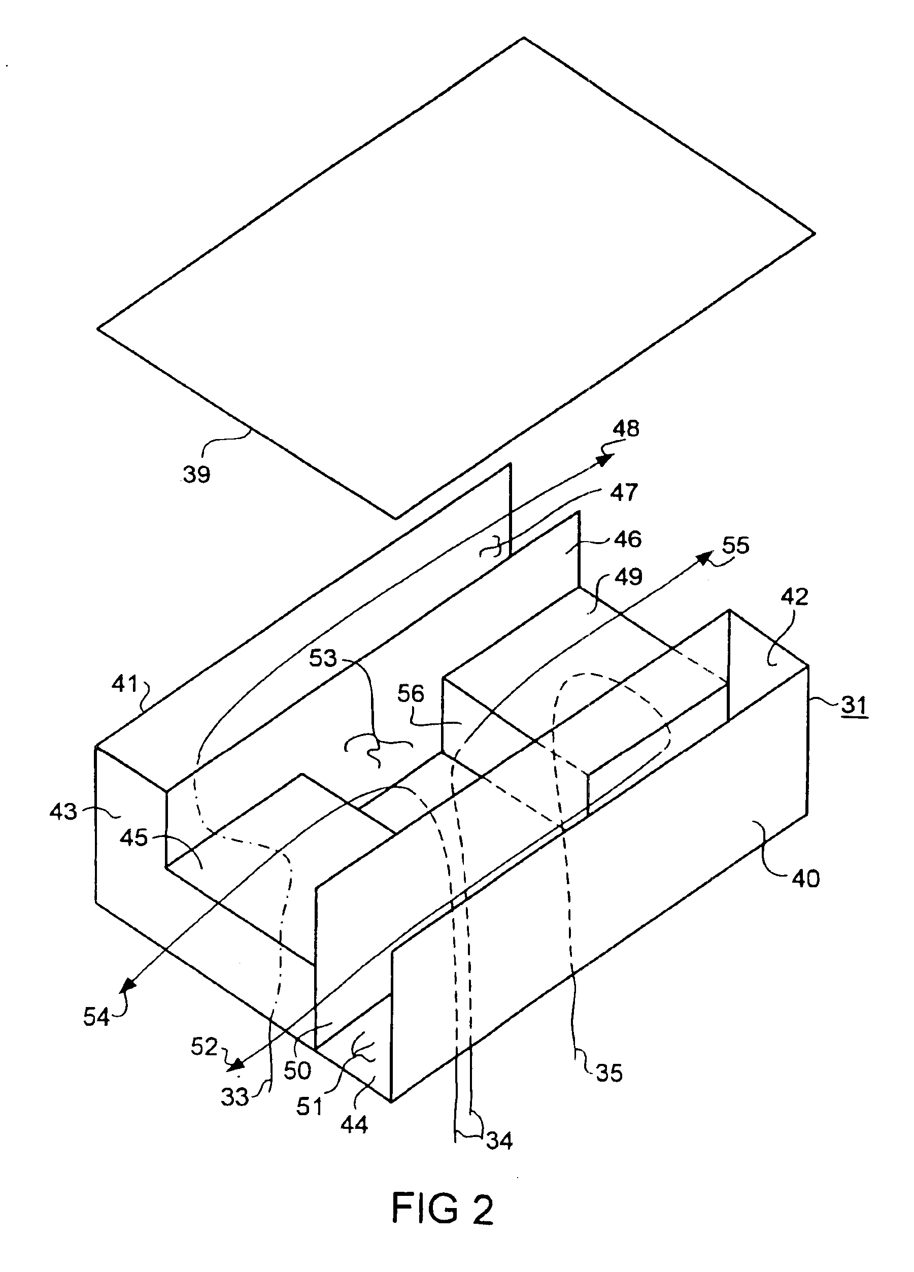
[0036]FIG. 2 shows, schematically, a switching gas damper 31 according to the invention, and the flow paths of the switching gas flows 33, 34 and 35 through it. For illustration, the closed cover 39 of the switching gas damper 31, which still comprises a front wall 40, a rear wall 41, a right-hand side wall 42, a left-hand side wall 43 and a bottom 44 which is closed away from the inlet openings, has been illustrated in a raised position. A deflection element 45 forms an outlet channel 47, which is open on the right-hand side of the switching gas damper 31, together with a left-hand side wall 43, a channel wall 46 which extends from the bottom 44 of the switching gas damper 31 to its cover 39 and a side part which cannot be seen. A further deflection element 49 with a side part 56 forms an outlet channel 51, which is open on the left-hand side of the switching gas damper 31, together with the right-hand side wall 42 and a channel wall 50 which extends from the bottom 44 of the switc...

third embodiment

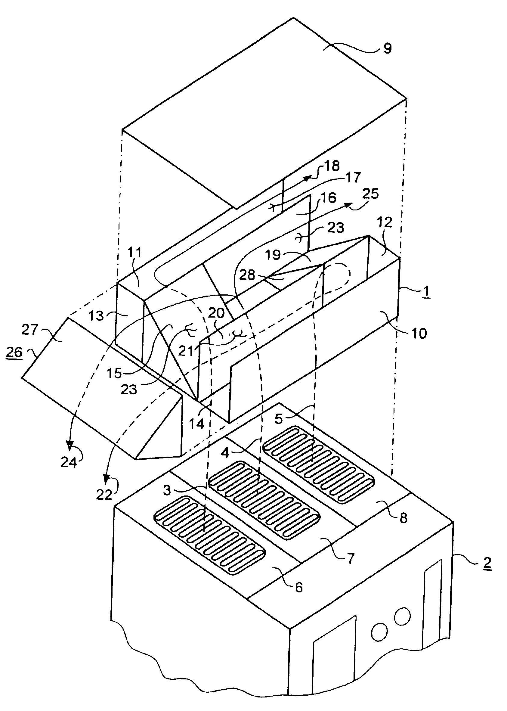
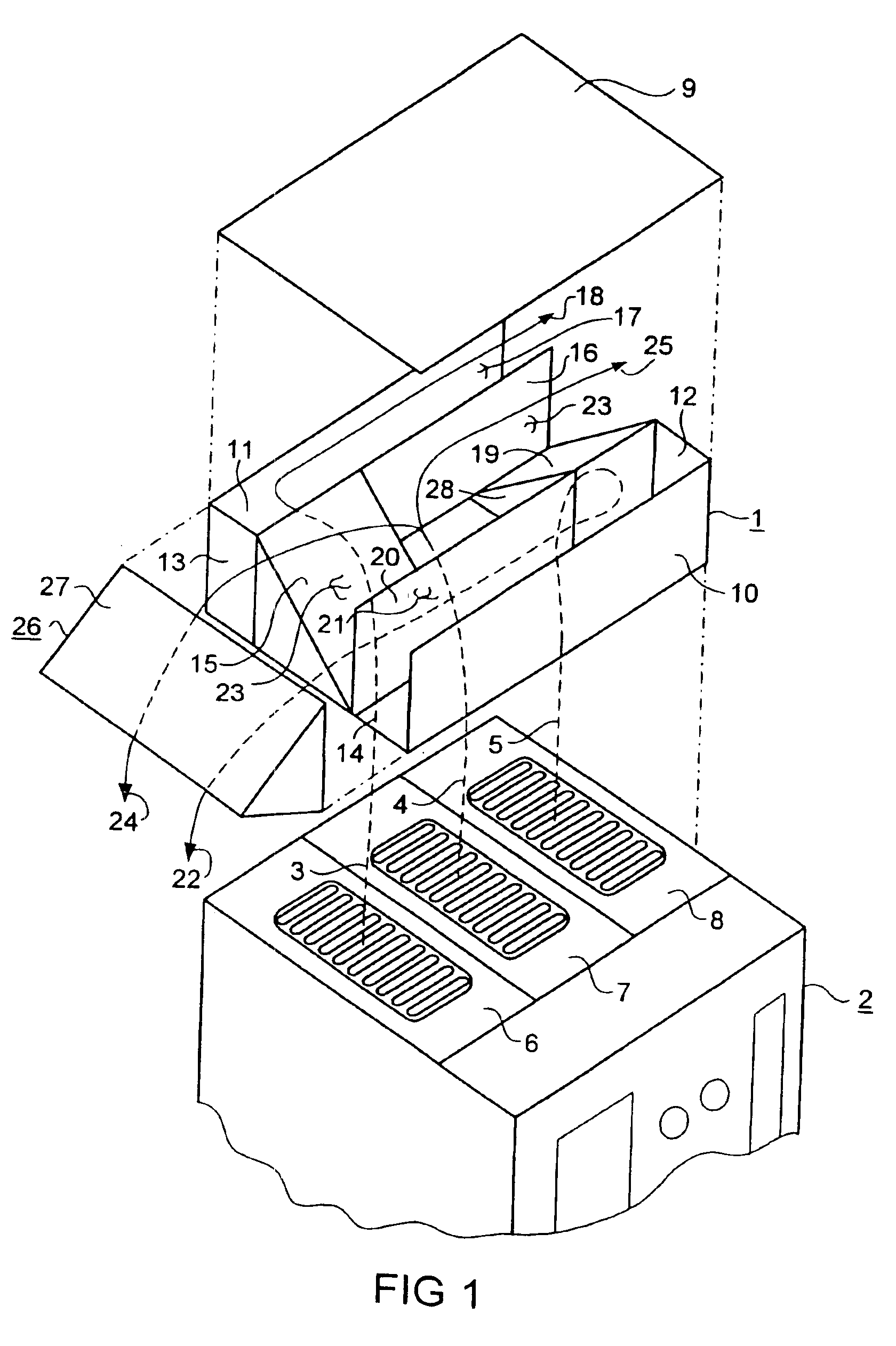
[0039]FIG. 3 shows, schematically and as a third embodiment, a switching gas damper 61 in its physical position with respect to a low-voltage power circuit breaker 62, and the flow paths of switching gas flows 63, 64, 65 from arcing chambers 66, 67, 68 through the switching gas damper 61. In a corresponding way to the illustration in FIG. 1, this is illustrated at a physical distance from the low-voltage power circuit breaker 62, in order to illustrate the paths of the switching gas flows 63, 64, 65 from the individual arcing chambers 66, 67, 68.

[0040]The switching gas damper 61 includes a closed cover 69, a front wall 70, a rear wall 71, a closed right-hand side wall 72, a closed left-hand side wall 73, and a bottom 74 which is closed away from the inlet openings. This embodiment of the switching gas damper 61 is broader than the low-voltage power circuit breaker 62. This means that the switching gas flows 63, 64 and 65 can be carried away downward through the closed side walls 72,...


PUM


Abstract

A switching gas damper for low-voltage power circuit breakers, is arranged as an attachment above the arcing chambers for additional damping, deionization and cooling of the switching gases. The switching gas damper includes a cuboid enclosure with separate inlet openings to receive switching gas flows from each arcing chamber in the low-voltage power circuit breaker. Separate outlet channels are formed by channel walls and/or by deflection elements and are routed on both sides of the power circuit breaker. A variable arrangement of the deflection elements and outlet channels makes it possible to produce a number of mutually separate flow paths, with different desired damping and cooling characteristics, as a function of the gas amounts that occur and of the characteristics of the arcing chambers that are used.

Description

[0001]This application is the national phase under 35 U.S.C. § 371 of PCT International Application No. PCT / DE00 / 01304 which has an International filing date of Apr. 23, 2000, which designated the United States of America, the entire contents of which are hereby incorporated by reference.FIELD OF THE INVENTION[0002]The invention generally relates to a switching gas damper for a multipole low-voltage power circuit breaker. More preferably, it relates to one which is arranged as an attachment above the parallel arcing chambers for additional damping, deionization and cooling of the switching gases, with the attachment having a cuboid enclosure with a front wall, a rear wall and a cover.BACKGROUND OF THE INVENTION[0003]Such a switching gas damper, as has been disclosed by EP 0 437 151 B1, has the object of assisting the effect of an arc quenching device for low-voltage power circuit breakers which switch in air. The arc quenching device causes switching arcs which occur during operatio...

Claims


Application Information

Patent Timeline
IPC IPC(8): H01H9/34H01H9/30H01H73/02H01H73/18
CPCH01H9/342H01H2009/348
Inventor BACH, MICHAELSCHMIDT, DETLEVSEBEKOW, MICHAELSEIDLER-STAHL, GUENTERTUERKMEN, SEZAI
Owner SIEMENS AG
Why Eureka
Try Eureka