Energy filter and electron microscope

a technology of energy filter and electron microscope, which is applied in the field of energy filter, can solve the problems of reducing the energy width reducing the efficiency of the electron beam,

Inactive Publication Date: 2005-11-01
JEOL LTD
View PDF19 Cites 19 Cited by
  • Summary
  • Abstract
  • Description
  • Claims
  • Application Information

AI Technical Summary

Benefits of technology

[0023]To achieve this object, the present invention provides an energy filter having a first filter and a second filter disposed behind the first filter, the first filter using a combination of electric and magnetic fields to select charged particles having a certain energy. The first filter is so controlled that a beam

Problems solved by technology

Consequently, it is difficult to obtain an electron beam having a narrow energy width.
Where the profile of the electron beam is elongated in the Y-direction by focusing the beam on the slit in the X-direction (along the width) by the aforementioned astigmatic focusing and unf

Method used


Image

  • Energy filter and electron microscope
  • Energy filter and electron microscope
  • Energy filter and electron microscope

Examples


Embodiment Construction

[0036]Energy filters and electron microscopes according to embodiments of the present invention are hereinafter described in detail with reference to the drawings.

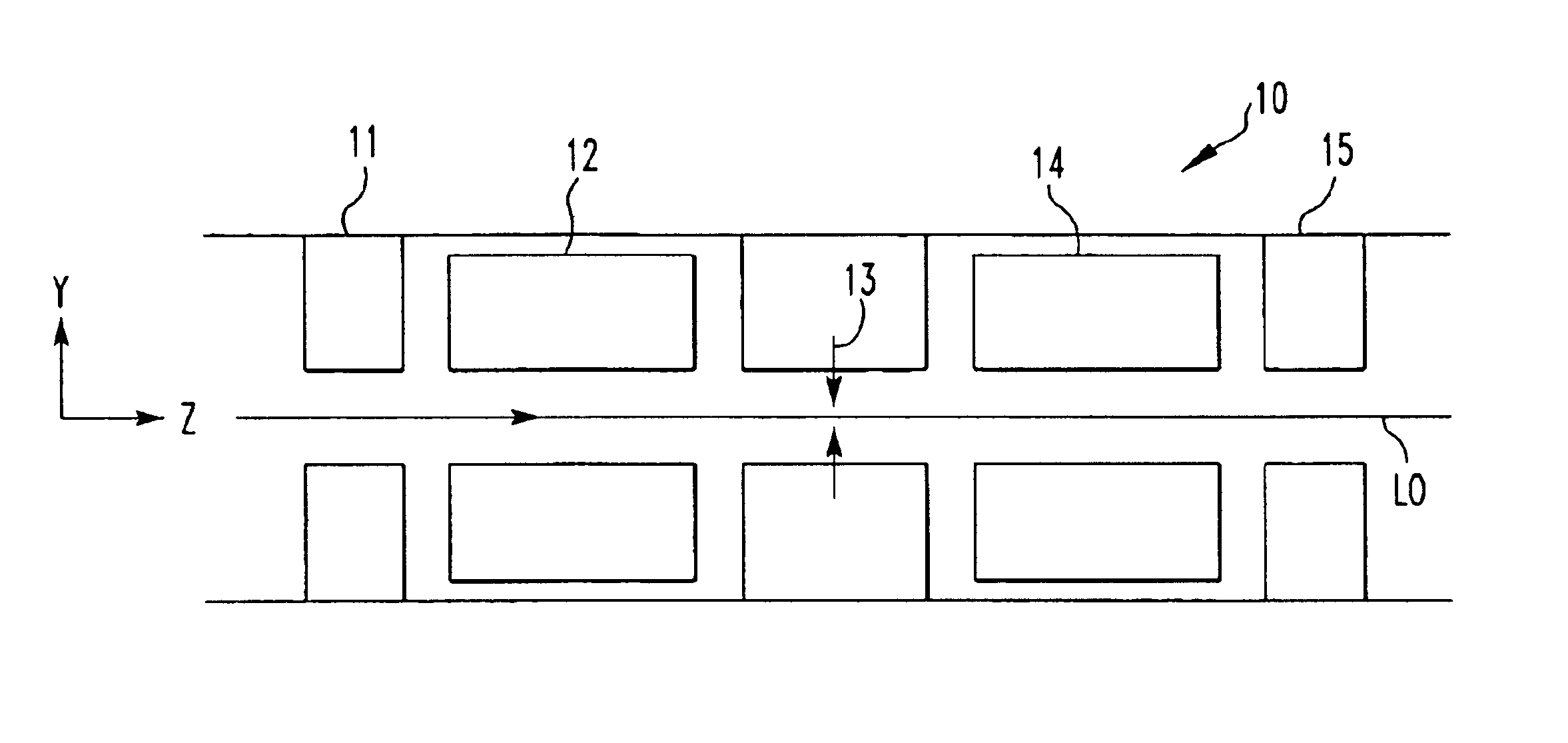
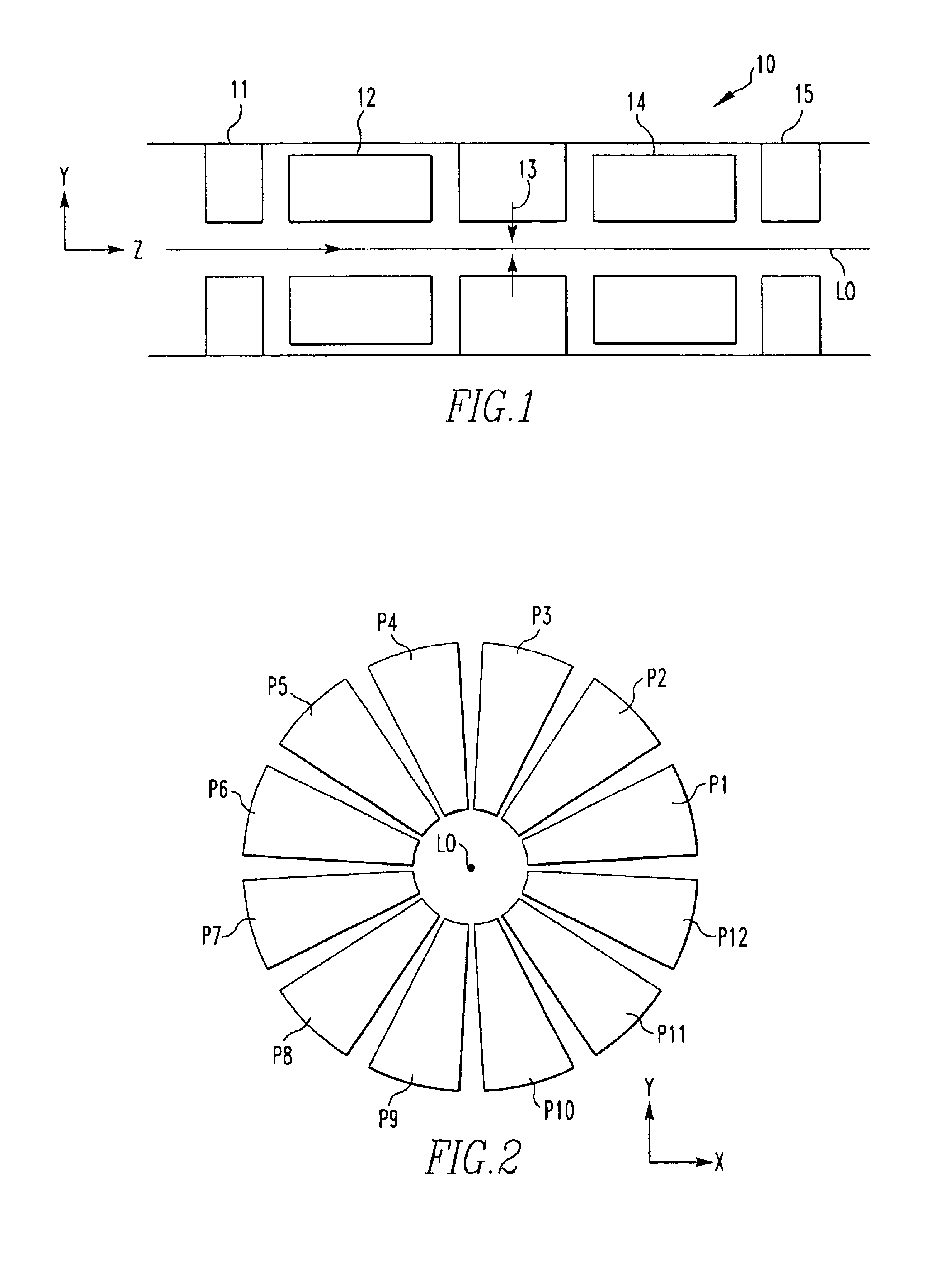
[0037]FIG. 1 shows the structure of an energy filter according to an embodiment. The energy filter, indicated by numeral 10, has a first stage of Wien filter 12, a slit 13, and a second stage of Wien filter 14 which are located in this order in the direction of travel of an electron beam along an optical axis L0. The electron beam is emitted from an electron gun (source of charged particles) and enters the first stage of Wien filter 12, which acts to focus the beam in one direction perpendicular to the optical axis L0. The Wien filters 12 and 14 are identical in shape. The slit 13 is located in the position where the beam is focused. The beam focused at the position of the slit 13 by the first stage of Wien filter 12 is made to enter the second stage of Wien filter 14. The second stage of Wien filter 14 is so designed that...


PUM


Abstract

An energy filter with reduced aberration. The energy filter has a first stage of filter for receiving an electron beam entering along the optical axis and for focusing the beam in one direction vertical to the optical axis and a second stage of filter positioned along the optical axis behind the first stage of filter. The beam once focused by the first stage of filter is made to enter the second stage of filter. In the second stage of filter, the orbit of the electron beam is inverted with respect to the focal point. The two stages of filters are identical in length taken along the optical axis. The first and second stages of filters have electric and magnetic quadrupole fields, respectively, along the optical axis. These quadrupole fields make an angle of 45 degrees to the optical axis to achieve astigmatic focusing.

Description

BACKGROUND OF THE INVENTION[0001]1. Field of the Invention[0002]The present invention relates to an energy filter for selectively passing charged particles having certain energies and to an electron microscope using this filter.[0003]2. Description of Related Art[0004]In recent years, a transmission electron microscope has been developed which has an energy filter positioned within the electron optical system for magnifying and projecting an electron beam transmitted through a specimen onto a fluorescent screen. With this transmission electron microscope fitted with such an energy filter, an electron microscope image of a specimen can be formed based on charged particles having only certain energies.[0005]In this electron microscope fitted with such an energy filter, the energy width of the electron beam directed at the specimen must be narrowed in order to enhance the energy resolution. For example, in an electron microscope using an accelerating voltage of hundreds of kilovolts, t...

Claims


Application Information

Patent Timeline
IPC IPC(8): H01J37/153H01J37/04H01J37/05G01Q30/06H01J37/26
CPCH01J37/05H01J37/153
Inventor LOPEZ, G. MARTINEZTSUNO, KATSUSHIGE
Owner JEOL LTD
Why Eureka
Try Eureka