Eureka AIR delivers breakthrough ideas for toughest innovation challenges, trusted by R&D personnel around the world.

Optical particle corrector

a technology of optical particle and corrector, applied in the field of corrector, to achieve the effect of low stability requirements

Inactive Publication Date: 2005-05-03
CEOS CORRECTED ELECTRON OPTICAL SYST
View PDF5 Cites 11 Cited by
  • Summary
  • Abstract
  • Description
  • Claims
  • Application Information

AI Technical Summary

Benefits of technology

[0031]The antisymmetrical choice has the decisive advantage that the corrector does not introduce aberrations with two-fold symmetry.
[0074]In this case, the further development of the invention described in the preferred embodiments is particularly advantageous, since the optical quality of the image further improves very large image aberrations, which can justify the extra design work.

Problems solved by technology

Furthermore, the corrector itself does not generate any 4th-order geometrical aberrations during correction.

Method used


Image

  • Optical particle corrector
  • Optical particle corrector
  • Optical particle corrector

Examples


Embodiment Construction

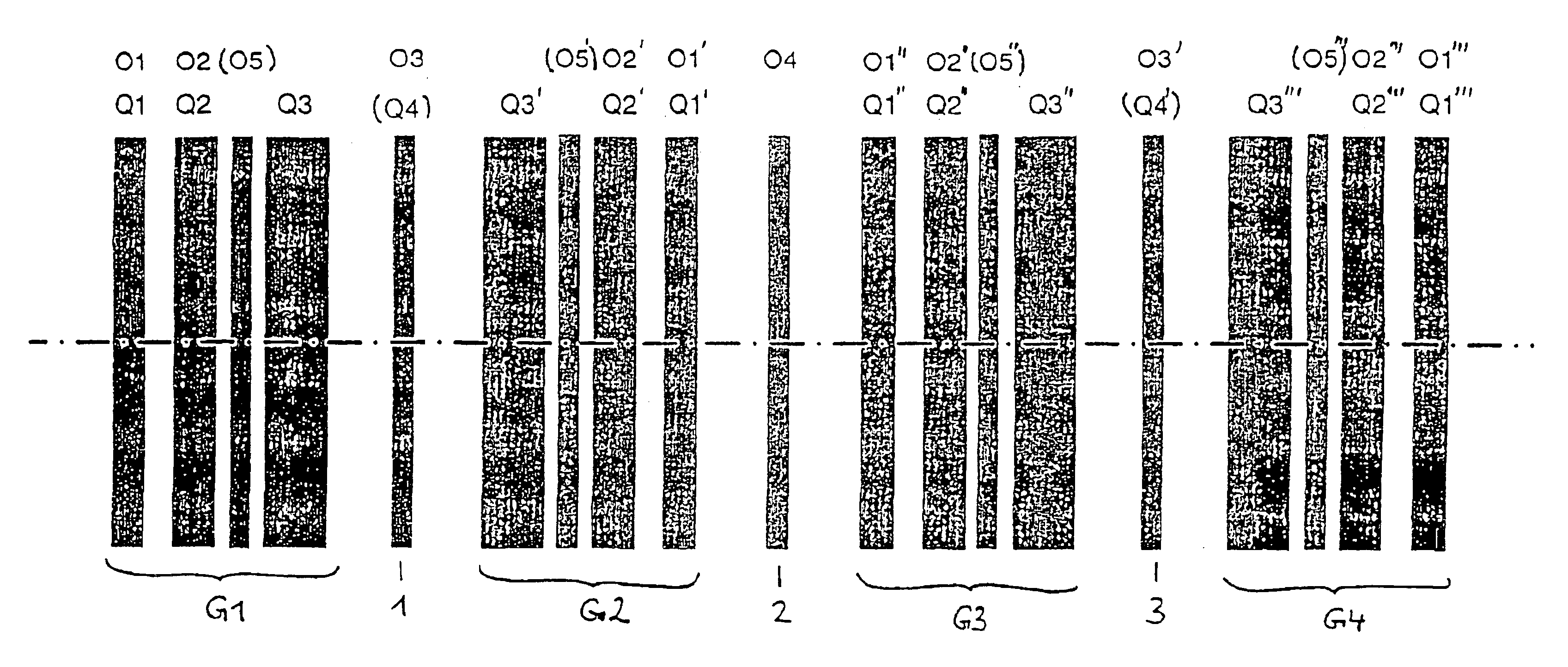
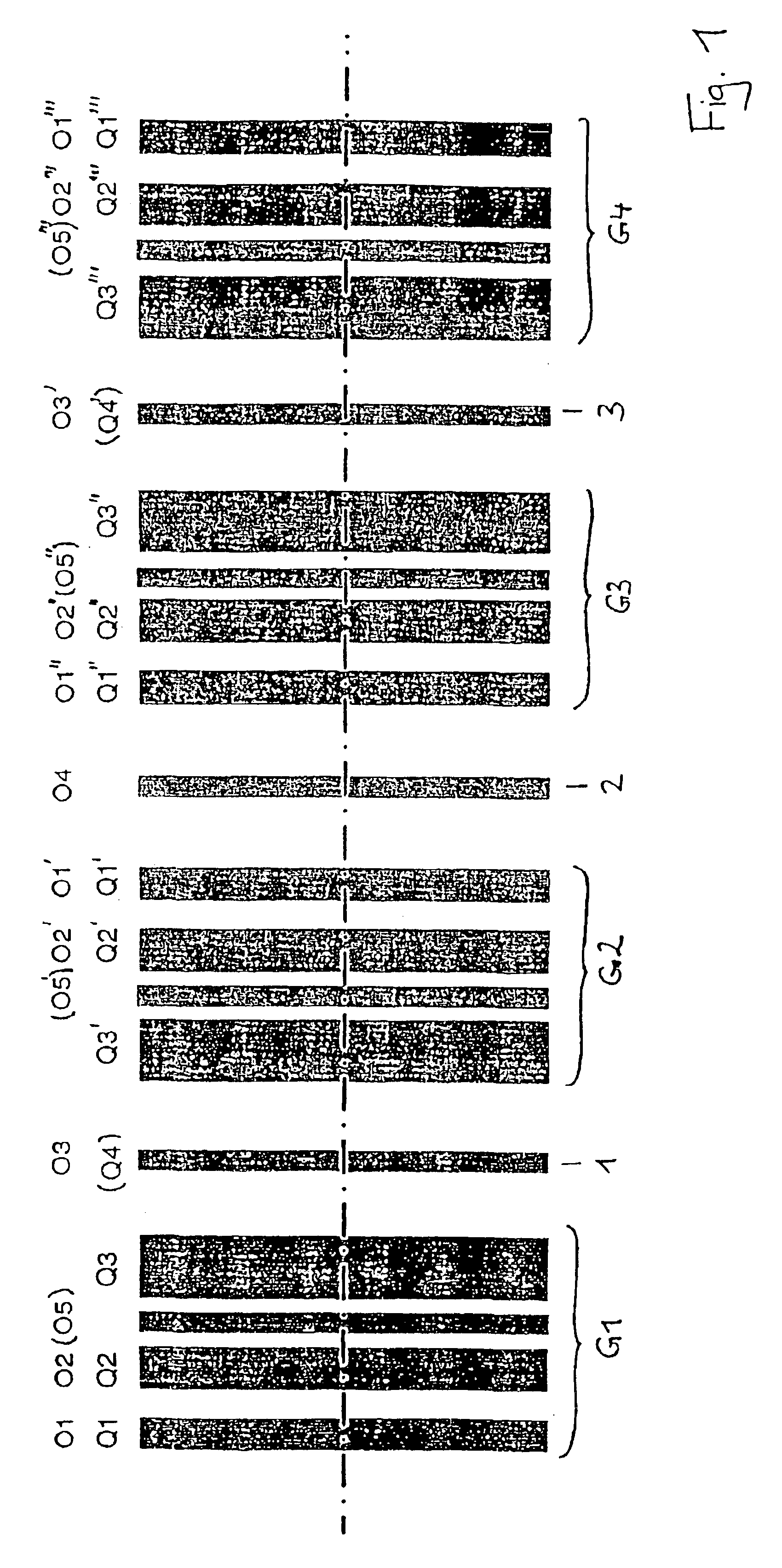
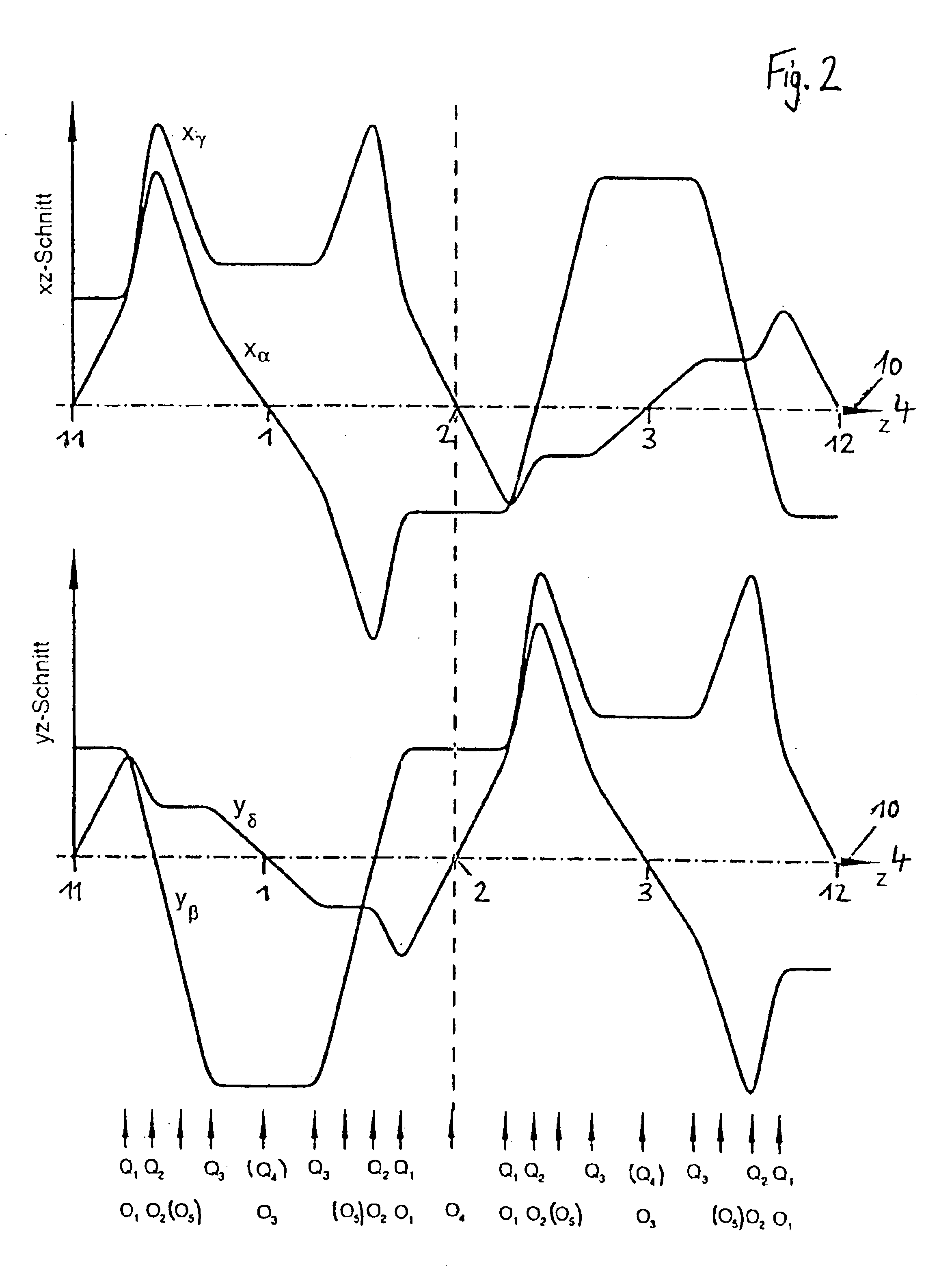
[0029]The corrector according to the present invention comprises four groups of three, which are arranged one behind the other along the optical axis and in each comprise three quadrupoles and two octupoles, The octupoles thereof are arranged such that their fields are superimposed on the quadrupole fields. The number of the respectively different elements is limited by the fact that the multipole elements from group to group in each case correspond to one another in pairs. The multiplicity of the elements is thereby reduced from 4 times 5 elements to 1 times 5 elements The multipole elements of the respective following group are therein positioned in each case in reverse sequence along the optical axis to the corresponding multipole elements of the respective preceding group.

[0030]The proposed embodiment describes a system with high symmetry, which is manifested in a double-symmetrical construction. Correspondingly, the first system half is symmetrical about the centre plane of the...


PUM


Abstract

An optical particle corrector with a straight optical axis for eliminating color and aperture aberrations in optical particle lenses includes multipole elements in the form of electric and / or magnetic quadrupole and octupole elements. There are at least twelve quadrupole elements and ten octupole elements, in which three quadrupole elements and two octupole elements are assembled into a group. These groups are arranged successively along the straight optical axis, in which a first symmetrical plane is defined between the first and second groups, a second symmetrical plane is defined between the second and third groups and a third symmetrical plane is defined between the third and fourth groups. The multipole elements from one group to another correspond to each other in pairs, in which the multipole elements of the corresponding following group are positioned in reverse order along the straight optical axis in comparison with the corresponding multipole elements of the preceding group. The structure and refractive powers of the multipole elements that correspond to each other are mirror-symmetrically configured relative to the corresponding symmetrical plane between the groups. At least two of the quadrupole elements generate electric-magnetic quadrupole fields, in which the quadrupole element are, preferably, arranged in a mirror-symmetrical manner relative to the second, or to all, symmetrical planes. An additional octupole element is arranged in the first and third symmetrical planes. The corrector enables the transmission of extremely large image fields, while the optical quality remains the same due to the fact image aberrations outside the axis can be corrected.

Description

BACKGROUND OF THE INVENTION[0001]1. Field of the Invention[0002]The invention relates to a corrector, which is equipped with multipole elements in the form of electrical and / or magnetic quadrupole and octupole elements, comprising a straight optical axis for eliminating the chromatic aberration and the divergence aberration of particle-optical lenses.[0003]2. Description of the Prior Art[0004]Particle-optical systems are successfully used both in enlarging systems, such as the electron microscopes, and in diminishing systems, such as electron-projection lithography. Compared with light-optical systems, they have the advantage of a substantially higher resolution, this magnitude being all the more marked the smaller the wavelength of the beams used. Where electron beams are used, this means a gain in resolution of a factor of 104 compared to light.[0005]A further improvement of the resolution of particle-optical systems requires a correction of the imagining lenses' own image aberrat...

Claims


Application Information

Patent Timeline
Patent Type & Authority Patents(United States)
IPC IPC(8): H01J37/153H01J37/04G01Q30/00H01L21/027
CPCH01J37/153H01J2237/1534
Inventor MULLER, HEIKOROSE, HARALD
Owner CEOS CORRECTED ELECTRON OPTICAL SYST
Why Eureka
Eureka Blog
Learn More