Resistance high-precision measuring system and method with combination of differential method and proportion method

A proportional method and resistance technology, which is applied in the field of low-cost high-precision resistance measurement systems, can solve the problems of difficulty in high-precision resistance measurement, reduce the cost of measurement systems, and cannot be obtained. The effect of reducing precision requirements

Active Publication Date: 2019-08-23
CENT SOUTH UNIV
View PDF4 Cites 7 Cited by
  • Summary
  • Abstract
  • Description
  • Claims
  • Application Information

AI Technical Summary

Problems solved by technology

However, this method is limited in practice, because it is not easy to obtain the same standard quantity with a small difference from the measured value, and sometimes it cannot be obtained.
[

Method used


Image

  • Resistance high-precision measuring system and method with combination of differential method and proportion method
  • Resistance high-precision measuring system and method with combination of differential method and proportion method
  • Resistance high-precision measuring system and method with combination of differential method and proportion method

Examples


Example Embodiment

[0052] Example one

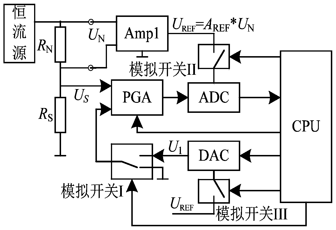
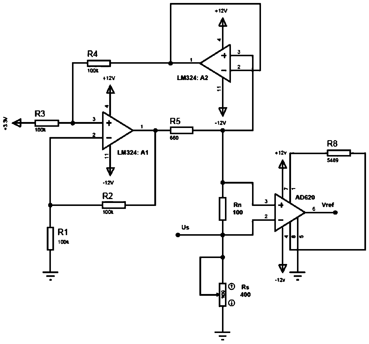
[0053] This embodiment provides a resistance measurement system combining the differential method and the proportional method, and its principle block diagram is as follows: figure 1 As shown, the specific circuit diagram is as image 3 Shown, including the measured resistance interface, constant current source, reference resistance R N , The first differential amplifier Amp1, the programmable gain amplifier PGA, the analog to digital converter ADC, the microprocessor CPU, the digital to analog converter DAC, the first analog switch I, the second analog switch II and the third analog switch III.

[0054] The first end of the reference resistor is connected to the first end of the measured resistance interface, the second end of the reference resistor is connected to the constant current source, and the second end of the measured resistance interface is grounded.

[0055] The two ends of the reference resistor are respectively connected to the two input terminals ...

Example Embodiment

[0083] Example two

[0084] In the first embodiment, since one end of the measured resistance is grounded, the voltage at the common connection end of the measured resistance and the reference resistance is the single-ended voltage to ground corresponding to the potential difference between the two ends of the measured resistance, which can be directly input to The first input of the programmable gain amplifier. In the second embodiment, the difference from the first embodiment is that the reference resistor and the resistance under test interface are exchanged, and a second differential amplifier is set between the resistance under test and the programmable gain amplifier, such as Figure 4 Shown. In the second embodiment, since both ends of the measured resistance have potential, it is necessary to set a second differential amplifier Amp-2 with a double gain between the measured resistance and the first input terminal of the programmable gain amplifier. The potential differenc...


PUM


Abstract

The invention discloses a resistance high-precision measuring system and method with combination of a differential method and a proportion method. The system comprises a constant current source, a reference resistor, a first differential amplifier, a programmable gain amplifier, an analog-to-digital converter, a microprocessor, a digital-analog converter and a measured resistor interface, the measured resistor interface is connected to a measured resistor, the reference resistor and the measured resistor are connected in series to form a serial connection branch circuit connected between the constant current source and the ground, two input terminals of the first differential amplifier are respectively connected with two terminals of the reference resistor, an output terminal of the firstdifferential amplifier is connected with a voltage reference terminal of the analog-to-digital converter, a first input terminal of the programmable gain amplifier is used for being connected to a to-ground single-end voltage of the measured resistor, a second input terminal of the programmable gain amplifier is connected with an analog output terminal of the digital-to-analog converter or the ground in a controlled manner, an output terminal of the programmable gain amplifier is connected with an analog input terminal of the analog-to-digital converter, and digital output terminals of the analog-to-digital converter and the digital-to-analog converter are both connected with the microprocessor. According to the system, the influence of power supply fluctuation can be overcome, the cost islow, and the measuring precision is high.

Description

technical field [0001] The invention relates to the field of sensors and detection technology and instruments, and specifically belongs to a low-cost and high-precision resistance measurement system and method combining a differential method and a proportional method. Background technique [0002] Accurate measurement of resistance is the basis for resistive sensors to achieve high-precision measurement. Resistive sensors are widely used in practical engineering, and it is also common in occasions where high-precision measurement of the sensed resistance is required. [0003] In the automatic detection system, the high-precision measurement of the resistance mostly adopts the digital measurement method, and the measurement device generally includes a microprocessor (CPU), an analog-to-digital converter (ADC), and a signal input circuit. The accuracy of the digital measurement system mainly depends on the accuracy or the number of bits of the ADC. Generally, the more the num...

Claims


Application Information

Patent Timeline
IPC IPC(8): G01R27/02G01R1/20G01R1/30
CPCG01R27/02G01R1/20G01R1/206G01R1/30G01R27/14G01R19/0084G01R19/0092G01R27/08
Inventor 刘少强李杜林樊晓平陈泽宇张熠铭
Owner CENT SOUTH UNIV
Why Eureka
Try Eureka