Liner ion beam bonding apparatus and array structure thereof

a technology of liner ion beam and ion beam, which is applied in the field of ion storage apparatus, can solve the problems of limiting the development of a portable mass spectrometry method, reducing the sensitivity of external ion sources, and limiting the number of ions that can be stored by the three-dimensional ion trap. achieve the effect of improving the capacity of mass resolution

Active Publication Date: 2015-06-18
SHIMADZU RES LAB SHANGHAI
View PDF11 Cites 10 Cited by
  • Summary
  • Abstract
  • Description
  • Claims
  • Application Information

AI Technical Summary

Benefits of technology

[0020]One of the technical problems to be solved by the present invention is to provide a simplified linear ion trapping apparatus, so as to solve problems that in a conventional substantial quadrupole rod linear ion trap, an assembly structu

Problems solved by technology

Meanwhile, peripheral components such as a vacuum cavity and an acquisition system also limit the development of a portable mass spectrometry method.
Due to a space charge effect caused by a coulomb repulsive force between ions, the number of ions that can be stored by the three-dimensional ion trap is relatively limited.
Moreover, introduction efficiency of ions having different mass-to-charge ratios has an obvious relationship with their introduction RF phases, which also causes an obvious decrease in sensitivity when an external ion source is used.
In addition, when an abundance spectrum of broken ions is used as a qualitative standard, the analysis structure thereof becomes unreliable due to the mass discrimination process.
As regards machining characteristics, electrodes of a linear ion trap need to be machined by using a high-precision curved-surface grinding machine, and the machining is more difficult than that of a three-dimensional ion trap.
In addition, assembly of electrodes 11, 12, 13, and 14 cannot be implemented by using a rotary insulator structure of a three-dimensional ion trap; to assemble the electrodes, special-shaped fit slot and key structures need to be provided on an internal cylindrical surface that supports an insulator, which makes the overall process more complex and exceeds the general precision machining level in China.
The red shift process detunes the motion resonance of ions and therefore slows down the ejection process, causing a loss of the mass resolution.
The advantage of this technology is that, this ion trap has no boundary electric field deficiency caused by the ejection slot, and therefore, can also be used as a common quadrupole mass filter; the disadvantage lies in that, ions are ejected

Method used


Image

  • Liner ion beam bonding apparatus and array structure thereof
  • Liner ion beam bonding apparatus and array structure thereof
  • Liner ion beam bonding apparatus and array structure thereof

Examples


embodiment 1

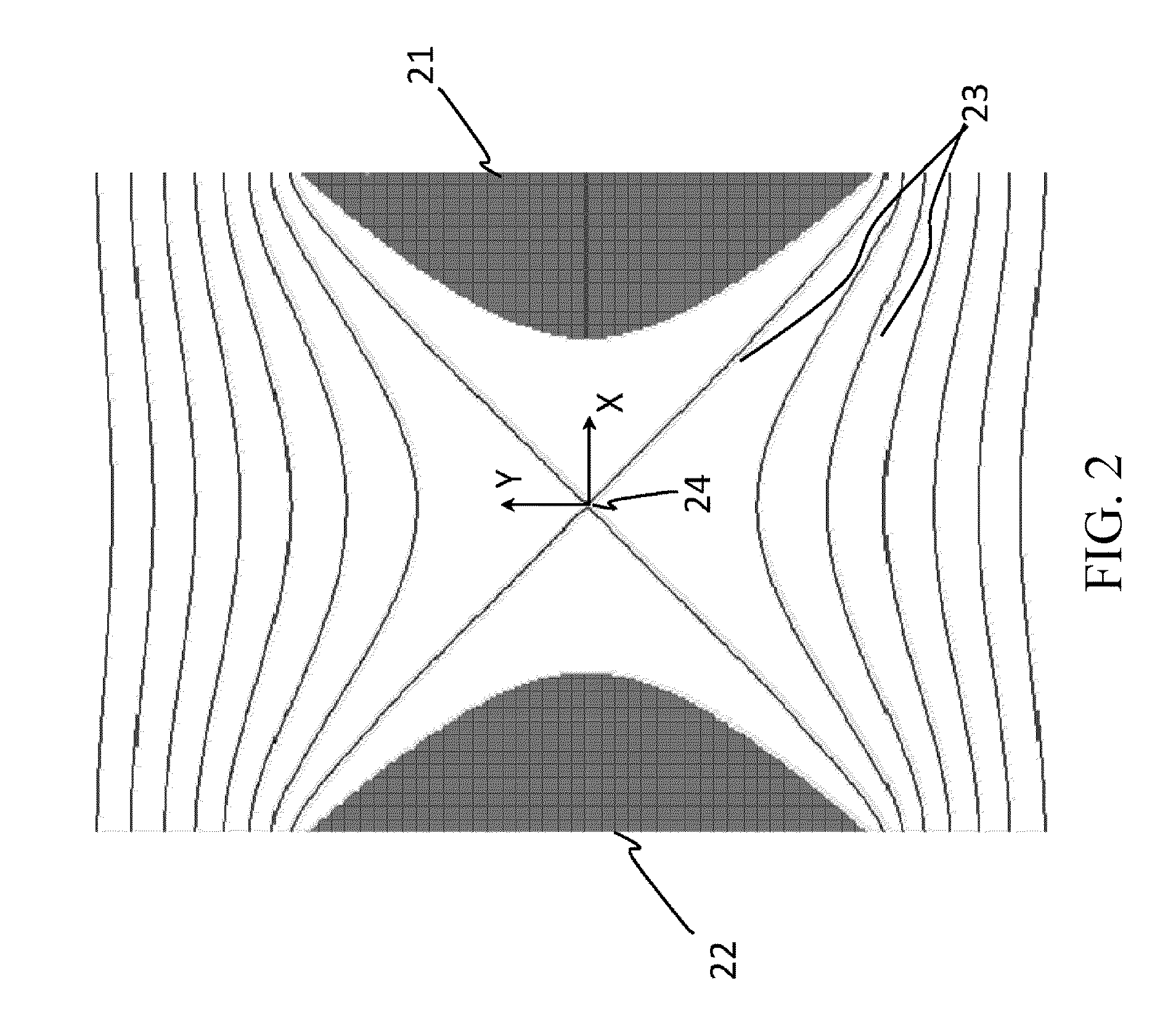
[0094]According to the embodiment of the present invention, auxiliary electrodes are deflected by an angle relative to RF electrodes, so as to further improve the intensity of a substantial quadrupole electric field between a RF electrode pair and suppress a multi-pole field parameter effect.

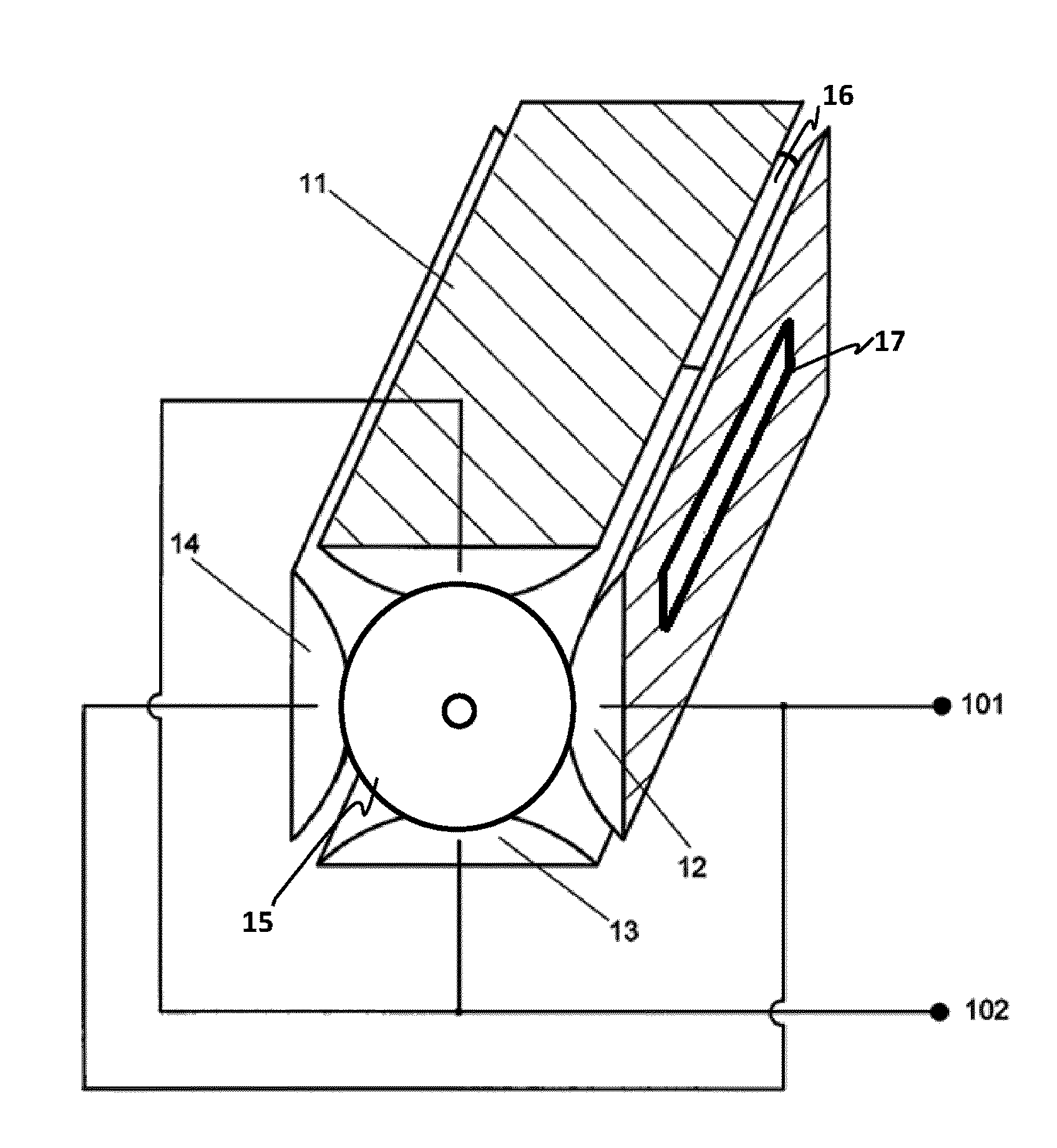
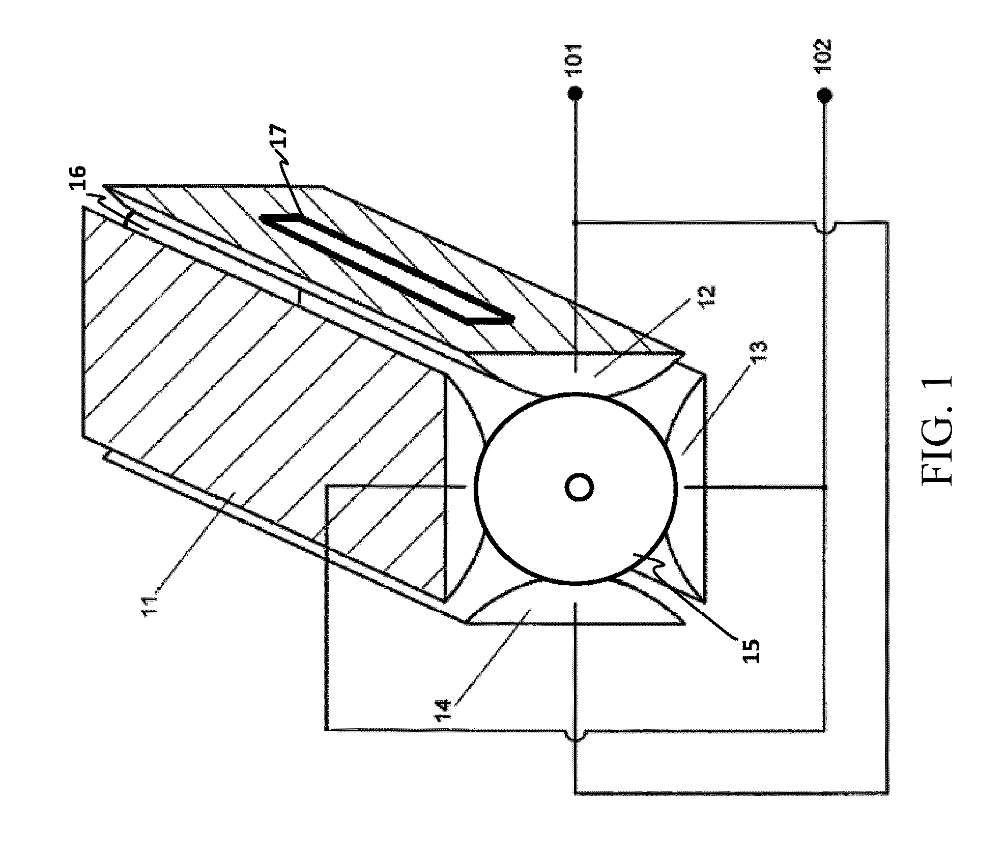
[0095]As Embodiment 1 of the present invention, referring to FIG. 5B, a proposed linear ion trapping apparatus includes an electrode system formed by a pair of hyperboloid rod main RF electrodes 501 and 502 and two auxiliary electrode pairs (503, 505) and (504, 506) located on two sides of the main RF electrodes 501 and 502. As a comparison, FIG. 5A shows a corresponding structure in the prior art. The position marked by 506 in FIG. 5B is the central axis of the ion trapping apparatus, and 506 is a main symmetry plane passing through the central axis. The pair of main RF electrodes 501 and 502 are oppositely disposed along two sides of the central axis, and extend along an axial direction. The c...

embodiment 2

[0106]According to the result shown in Embodiment 1, after the auxiliary electrodes are rotated by a deflection angle relative to the symmetry plane of the main RF electrodes, the quadrupole field factor of the device and the resolution capability of the device used as a mass analyzer are both improved. However, for a common linear ion trapping apparatus, including the design structure shown in Embodiment 1, the main RF electrode part thereof has both x symmetry and y symmetry. In other words, for these linear ion trapping apparatuses, in any cross section perpendicular to the straight or bent central axis thereof, the left and right sides are symmetric in the ion ejection direction, and moreover, the linear ion trapping apparatuses are also symmetric in the direction perpendicular to the ion ejection direction. In the symmetric structure, both the main RF voltage and excitation voltage are balanced alternating signals, which have no influence on a mean coordinate of a large quantit...

embodiment 3

[0116]The dominant ejection direction of an ion trap mass analyzer can be adjusted conveniently by directly modifying the DC voltage on each electrode in the trap. However, in such modification, a high DC component is mixed in the electric field of the analyzer, causing mass discrimination on ions with a higher mass-to-charge ratio and a lower higher mass-to-charge ratio. To solve this problem, a field adjustment electrode structure may be introduced. As shown in FIG. 15, a field adjustment electrode 1501 of this embodiment is located on an external side of a main RF electrode 71 on one side of the axis of an ion trapping apparatus, and is symmetrical about a symmetry plane of main RF electrodes. The symmetry ensures that an electric field applied on the field adjustment electrode does not produce obvious disturbance, which is perpendicular to the ejection direction, on ions that move on the symmetry plane of the linear ion trapping apparatus, In addition, this embodiment further in...


PUM


Abstract

A linear ion beam bonding apparatus and an array structure thereof, comprising a pair of primary radiofrequency electrodes (501 and 502) extending along the axial direction and oppositely arranged on two sides of the central axis of the linear ion beam bonding apparatus. Section patterns on different section planes of each of the primary radiofrequency electrodes (501 and 502) and perpendicular to the central axis are all kept symmetric via a primary symmetric plane (506) of the central axis. Radiofrequency voltages attached to the primary radiofrequency electrodes (501 and 502) are of identical phases. An ion extraction groove (84) is arranged on at least one of the primary radiofrequency electrodes (501 and 502), while at least one pair of auxiliary electrodes (503 and 505) are arranged on two sides of the pair of primary radiofrequency electrodes (501 and 502). The auxiliary electrodes (503 and 505) are arranged in duality to the primary symmetric plane (506). At least one of the auxiliary electrodes (503 and 505) is provided with a finite number of symmetric planes (507), while a minimal angle greater than 0 degrees and less than 90 degrees is provided between each symmetric plane (507) and the symmetric plane (506) of the primary radiofrequency electrodes (501 and 502). By means of this, a quadrupole field component of an ion beam bonding radiofrequency electric field within the ion beam bonding apparatus is strengthened.

Description

BACKGROUND[0001]1. Technical Field[0002]The present invention relates to an ion storage apparatus capable of being used as a mass analyzer, and in particular, to a linear ion trapping apparatus capable of being used as a linear ion trap mass analyzer, and an array structure thereof.[0003]2. Related Art[0004]The mass spectrometry method is one of important analysis methods in the current mainstream fields of chemistry and life science. As a main analysis apparatus of the mass spectrometry method, a mass spectrometry instrument has been developed from a desktop type to a portable type, and even to a handheld type in recent years. The development of these new mobile devices has new requirements for miniaturization of major components of the mass spectrometry instrument, especially, the mass analyzer which functions as the core of the mass spectrometry instrument. The main objective is to ensure the basic analysis performance of the mass analyzer while ensuring the miniaturization and s...

Claims


Application Information

Patent Timeline
IPC IPC(8): H01J49/42H01J49/00G01N27/62
CPCH01J49/423H01J49/0027H01J49/427H01J49/063H01J49/4255
Inventor JIANG, GONGYUSUN, WENJIAN
Owner SHIMADZU RES LAB SHANGHAI
Why Eureka
Try Eureka