Chromatic aberration corrector and electron microscope
a technology of electron microscope and corrector, which is applied in the direction of instruments, mass spectrometers, beam deviation/focusing by electric/magnetic means, etc., can solve the problems of increasing the perturbation amount of the electron beam, deteriorating the ultimate resolution of the electron microscope, etc., and achieves the effect of reducing length or thickness and improving resolution
- Summary
- Abstract
- Description
- Claims
- Application Information
AI Technical Summary
Benefits of technology
Problems solved by technology
Method used
Image
Examples
first embodiment
1. First Embodiment
1.1. Configuration of Chromatic Aberration Corrector
[0045]First, the configuration of a chromatic aberration corrector associated with a first embodiment of the present invention is described with reference to some drawings. This corrector is for use with an electron microscope that irradiates a subject to be observed with an electron beam and produces a magnified image of the subject. Examples of electron microscope include a transmission electron microscope (TEM), a scanning transmission electron microscope (STEM), and a scanning electron microscope (SEM).
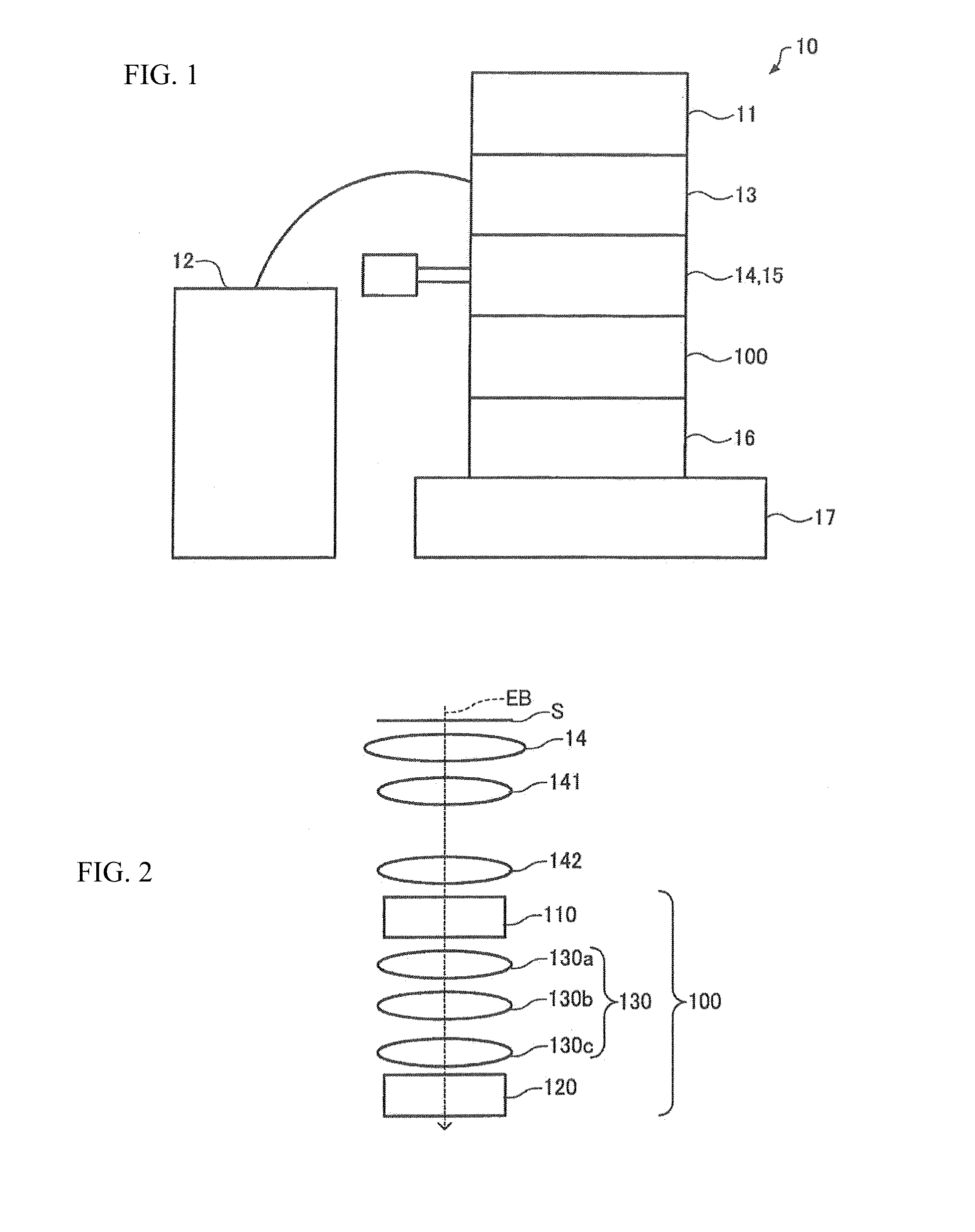
[0046]FIG. 1 shows the configuration of an electron microscope 10 equipped with a chromatic aberration corrector 100 associated with the first embodiment. A case in which the chromatic aberration corrector 100 is equipped in a transmission electron microscope is described. That is, the chromatic aberration corrector 100 is adapted for use with a transmission electron microscope.
[0047]The electron microscope 10 ...
first modification
(1) First Modification
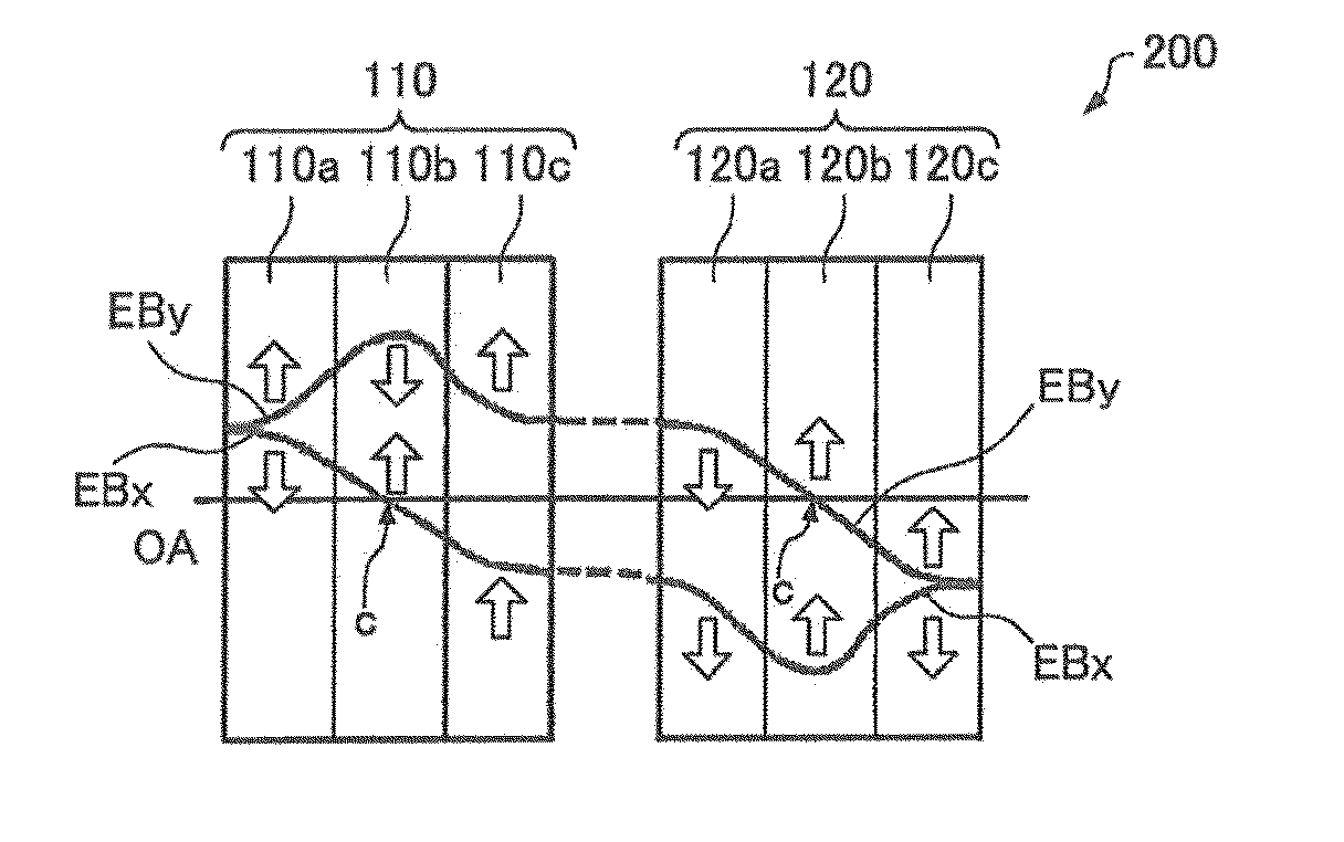
[0142]A first modification is described. FIG. 10 shows the optical system of a chromatic aberration corrector, 200, associated with the first modification. FIGS. 11A-11D show a first multipole element 110 and a second multipole element 120 of the chromatic aberration corrector 200. FIG. 11A shows the configuration of the chromatic aberration corrector 200. In FIG. 11A, an X orbit EBx is shown as a typical orbit of an electron beam EB in the X-direction. A Y orbit EBy is shown as a typical orbit of the beam EB in the Y-direction. FIG. 11B shows two-fold astigmatism components in various portions 110a, 110b, 110c, 120a, 120b, and 120c of the multipole elements 110 and 120. FIG. 11C shows lens effects produced in the various portions 110a, 110b, 110c, 120a, 120b, and 120c of the multipole elements 110 and 120. FIG. 11D shows two-fold chromatic astigmatism components produced in the first multipole element 110 and second multipole element 120. Those members of the ...
second modification
(2) Second Modification
[0146]A second modification is next described. FIG. 12 shows the optical system of a chromatic aberration corrector, 300, associated with the second embodiment. Those members of the chromatic aberration corrector 300 which are similar in function with their respective counterparts of the aforementioned chromatic aberration corrector 100 are indicated by the same reference numerals as in the above-cited figures and a detail description thereof is omitted.
[0147]The chromatic aberration corrector 300 includes a third multipole element 310 for superimposing an electric field of 4-fold symmetry on the first electromagnetic field produced by the first multipole element 110 and a fourth multipole element 320 for superimposing an electric field of 4-fold symmetry on the second electromagnetic field produced by the second multipole element 120. Consequently, the chromatic aberration corrector 300 can correct spherical aberration in addition to chromatic aberration.
[014...
PUM
 Abstract
Description
Claims
Application Information
 - R&D
- Intellectual Property
- Life Sciences
- Materials
- Tech Scout
- Unparalleled Data Quality
- Higher Quality Content
- 60% Fewer Hallucinations
Browse by: Latest US Patents, China's latest patents, Technical Efficacy Thesaurus, Application Domain, Technology Topic, Popular Technical Reports.
© 2025 PatSnap. All rights reserved.Legal|Privacy policy|Modern Slavery Act Transparency Statement|Sitemap|About US| Contact US: help@patsnap.com


