
High-frequency relay having a conductive and grounding base covering at least a bottom surface of a body

Inactive Publication Date: 2005-11-01
FUJITSU COMPONENENT LTD
View PDF8 Cites 18 Cited by
  • Summary
  • Abstract
  • Description
  • Claims
  • Application Information

AI Technical Summary

Benefits of technology

[0026]A more specific object of the present invention is to provide a high-frequency relay that exhibits an excellent isolation characteristic.
[0028]According to the present invention, the high-frequency relay can exhibit an excellent isolation characteristic.
[0049]According to the present invention, when the relay is mounted on a substrate, the base of the relay and a pattern formed on the substrate can surely be prevented from interfering with each other.

Problems solved by technology

As a frequency of the signal becomes higher, the leakage increases.
Therefore, a leakage of a signal is large between the magnetic circuit component and each of the contacts 4d and 5a, between the magnetic circuit component and each of the terminals 4f and 5b connected to the contacts 4d and 5a, respectively, and between the terminals 4f and 5b. Therefore, the above-mentioned methods, such as enlarging a clearance between the contacts 4d and 5a, are not necessarily effective.
In addition, to extremely enlarge the clearance between the contacts 4d and 5a makes an obstacle hindering miniaturization needs for the relay.
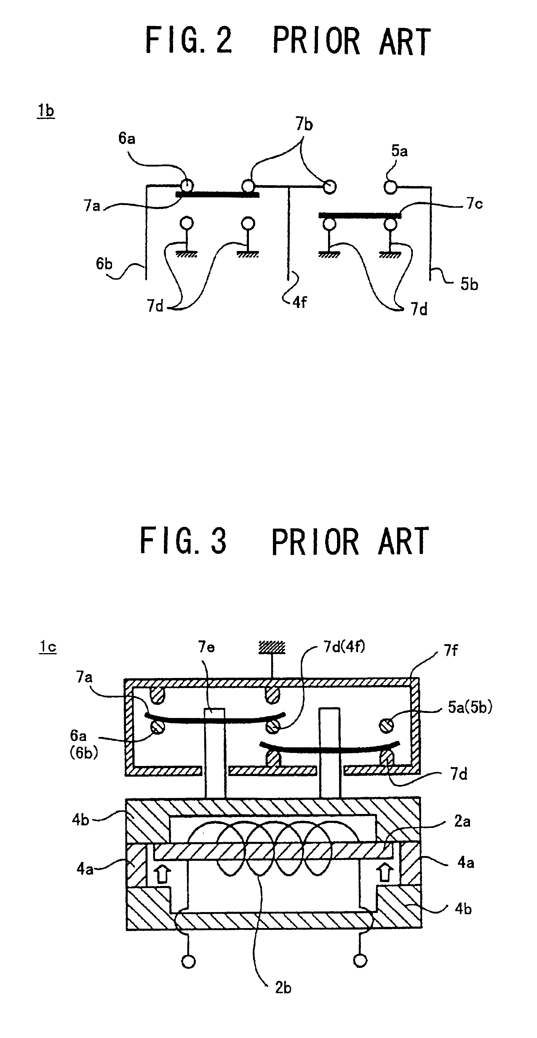
In these examples, however, the relay 1c shown in FIG. 3 has a structure in which the contact unit and the magnetic circuit are separated; this hinders miniaturization of the relay.
Also, as in the relay 1d shown in FIG. 4, the grounded shield plates 7f make a complicated structure; thus, the components cannot be easily manufactured and mounted.
However, the heretofore-described conventional relays do not necessarily provide a satisfactory isolation characteristic.

Method used


Image

  • High-frequency relay having a conductive and grounding base covering at least a bottom surface of a body
  • High-frequency relay having a conductive and grounding base covering at least a bottom surface of a body
  • High-frequency relay having a conductive and grounding base covering at least a bottom surface of a body

Examples


first embodiment

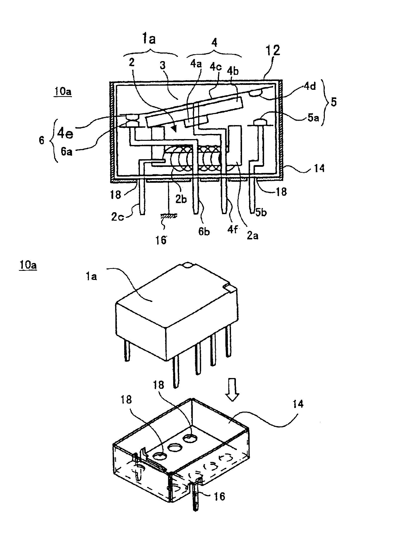
[0127]As shown in FIG. 8A to FIG. 8C, a relay 10a according to the present invention is a relay in which the present invention is applied to the conventional relay 1a shown in FIG. 1A.

[0128]The relay 10a comprises the body 1a of the relay, and a metal base 14. The body 1a contains the contact unit 3 in which the contact (make / break) state switches according as an energization to the coil 2b. The contact terminals 4f, 5b and 6b connected to the contact unit 3, and the coil terminal 2c, are protruded from a bottom surface of a resinous cover 12 covering these elements. The metal base 14 is formed in a box shape covering a bottom surface and four sides of the body 1a and opening upward. Ground terminals 16 realizing a grounding function are mounted on the base 14. The ground terminals 16 are terminals inserted into through holes of a substrate not shown in the figure. Insertion holes 18 are formed in a bottom surface of the base 14. The terminals 2c, 4f, 5b and 6b of the body 1a are in...

fourth embodiment

[0145]The cover 34 of the relay 10c according to the present fourth embodiment can be formed from the metal plate 20 by deep drawing, for example as shown in FIG. 28. Alternatively, the cover 34 can be formed from the metal plate 20 by bending, for example as shown in FIG. 29.

[0146]Next, as shown in FIG. 30A and FIG. 30B, a relay 10d according to a fifth embodiment of the present invention has substantially the same structure as the relay 10c according to the foregoing fourth embodiment, but is different from the relay 10c in that long foldable projections 34b are provided on opposing sides 34c of the cover 34.

[0147]Each of the base 14 and the cover 34 is formed from the metal plate by bending, and the ground terminals 16 of the base 14 are bent from the metal plate. In this course, bending the ground terminals 16 leaves defective parts, i.e., openings (indicated by arrows A in FIG. 30A) in the bottom surface 14a of the base 14. However, when the cover 34 containing the body 1a is i...


PUM


Abstract

A high-frequency relay comprises a body containing a contact unit having at least one contact terminal protruding from a bottom surface of the body, contact states switched according to energization of a coil and a base covering at least a bottom surface of the body. The contact unit is connected with at least one contact terminal. The base has a grounding function and includes a conductive layer.

Description

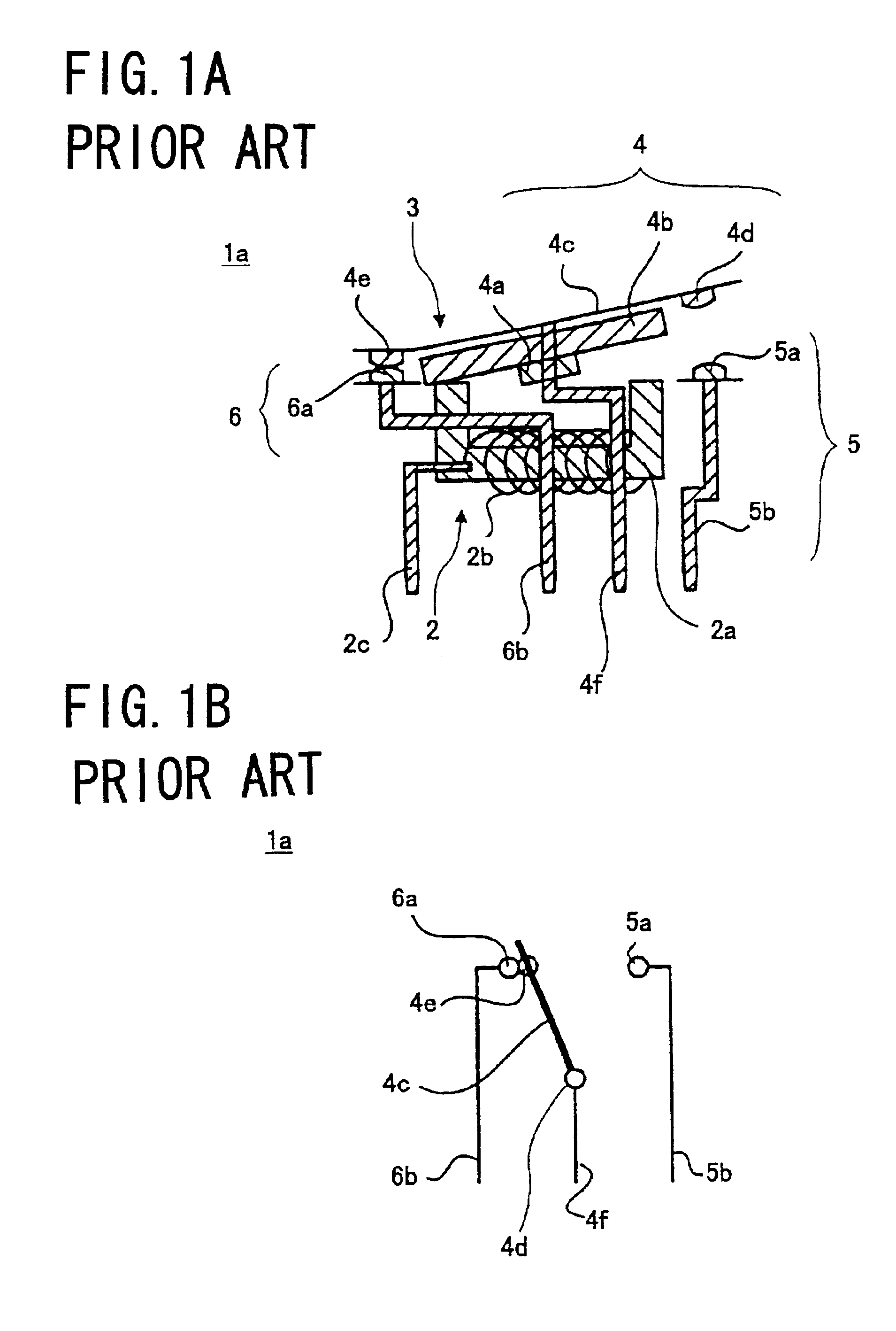
BACKGROUND OF THE INVENTION[0001]1. Field of the Invention[0002]The present invention generally relates to a high-frequency relay, and more particularly, to a high-frequency relay switching a high-frequency signal.[0003]2. Description of the Related Art[0004]FIG. 1A and FIG. 1B illustrate an example of a high-frequency relay.[0005]A high-frequency relay 1a comprises an electromagnet unit 2 and a contact unit 3.[0006]The electromagnet unit 2 comprises an iron core 2a, a coil 2b wound around the iron core 2a, and a coil terminal 2c connected to the coil 2b. The coil terminal 2c hangs down so as to be connected to a substrate not shown in the figure.[0007]The contact unit 3 comprises a moving contact unit 4, a fixed make contact unit 5 and a fixed break contact unit 6. The fixed make contact unit 5 and the fixed break contact unit 6 are provided at positions opposite both ends of the moving contact unit 4.[0008]The moving contact unit 4 includes an armature 4b provided opposite the ele...

Claims


Application Information

Patent Timeline
IPC IPC(8): H01H50/10H01H50/00H01H9/12H01H9/00H01H45/04H01H45/10H01H50/02H01H50/04H01H50/18
CPCH01H50/10H01H9/12
Inventor NAKAMURA, AKIOKURATA, YOSHINORISASO, HIROFUMI
Owner FUJITSU COMPONENENT LTD
Learn More