Pilot valve operated reciprocating fluid exchange device and method of use

a reciprocating fluid exchange and pilot valve technology, applied in liquid handling, separation processes, packaged goods types, etc., can solve the problem of needing a fluid exchange system, and achieve the effect of being very portable and useful

Inactive Publication Date: 2005-11-08
VIKEN JAMES P
View PDF25 Cites 8 Cited by
  • Summary
  • Abstract
  • Description
  • Claims
  • Application Information

AI Technical Summary

Benefits of technology

[0014]One object of the present invention is a device which permits an efficient change between different fresh fluids (grades, additive packages, etc.) between or during exchange procedures. The limited volumetric capacity of the pump assembly and associated conduit results in a limited amount of the previous different fresh fluid charge held within the exchange apparatus.
[0015]One object of the invention is to provide a fluid exchanger which is self-powered by pressure in the accessed fluid circulation circuit thereby removing the need to connect the exchanger to the electrical system of a vehicle being serviced or to an external electrical outlet or compressed air supply. This allows a high degree of portability and minimizes the potential of electronic component damage.
[0018]Another object of the invention is to also provide a fluid control mechanism which is reliably activated and more durable for exchanging the fluid of high fluid flow, high fluid pressure fluid circulation circuits such as large, commercial trucks or other industrial or commercial equipment or machines used in manufacturing.
[0021]One object of this invention is to provide a simple mechanical automatic bypass valving system which requires no source of electrical power.

Problems solved by technology

One unresolved problem has been the need for a fluid exchange system which requires no external power source such as an electric motor or compressed air.

Method used


Image

  • Pilot valve operated reciprocating fluid exchange device and method of use
  • Pilot valve operated reciprocating fluid exchange device and method of use
  • Pilot valve operated reciprocating fluid exchange device and method of use

Examples


Embodiment Construction

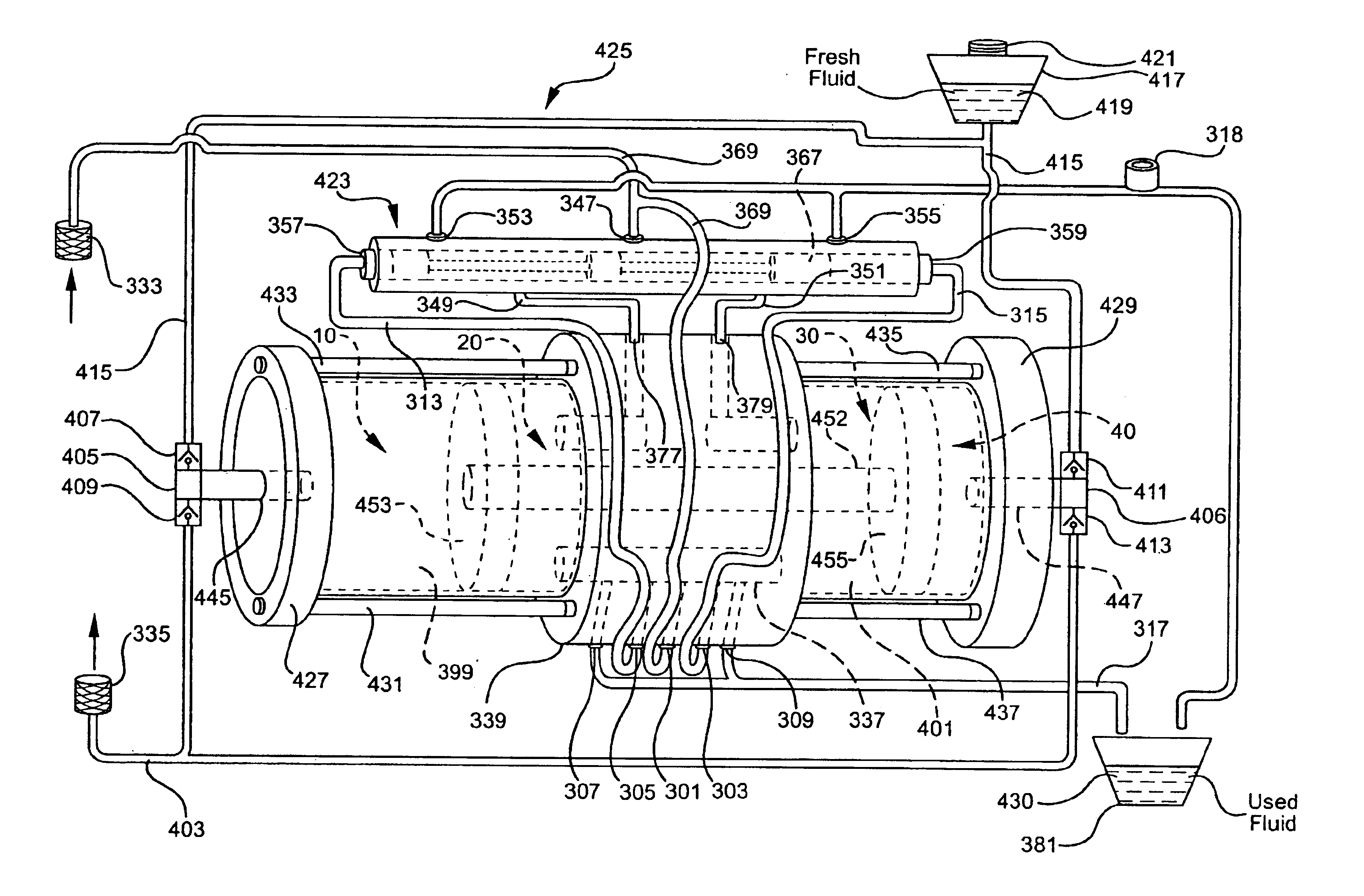
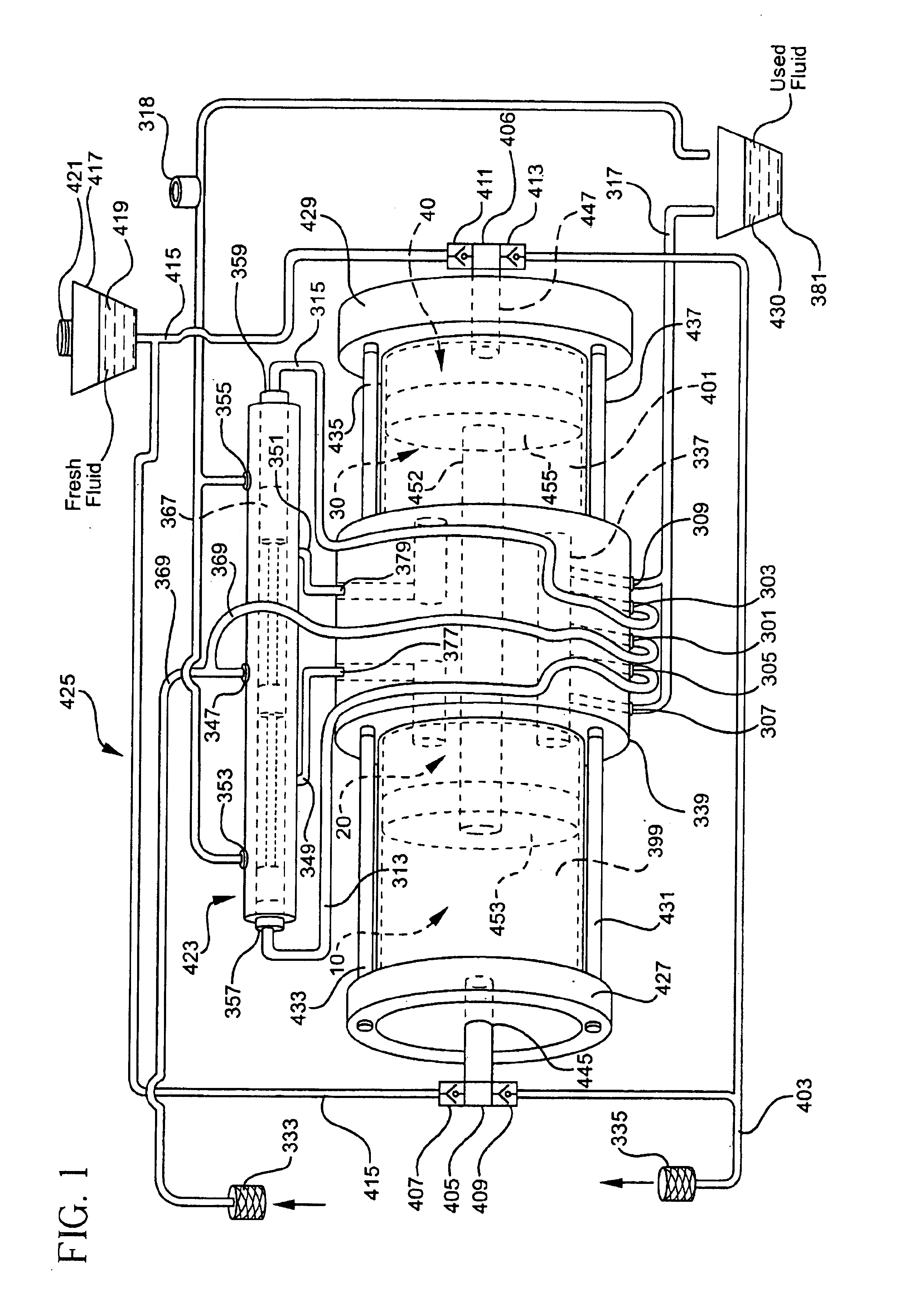
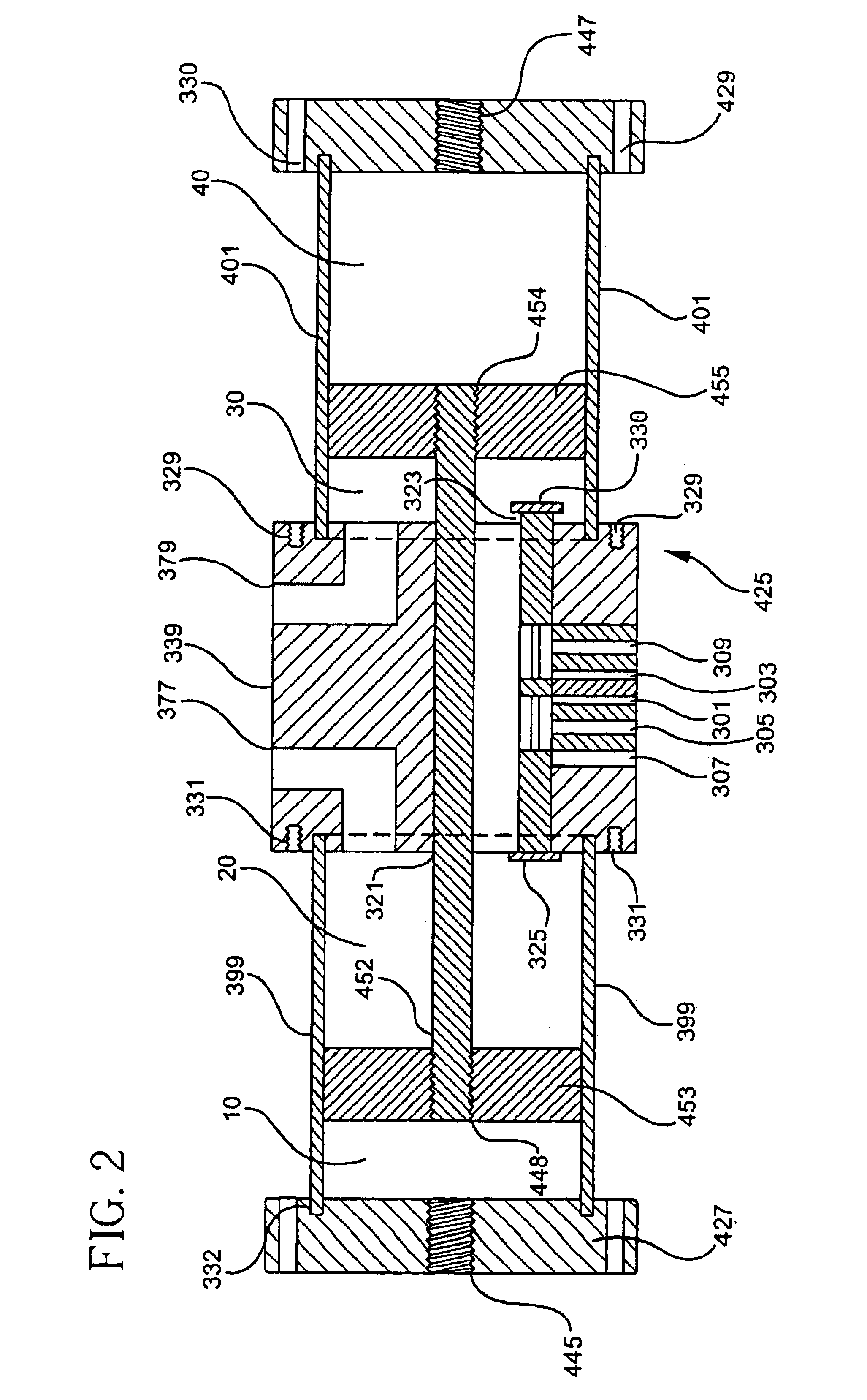
[0033]As shown in FIG. 1, one embodiment of the invention includes a pump 425 including two reciprocating pistons 453, 455 linked by a connecting rod 452 within a cylinder block 339 as further depicted in FIG. 2. Pump 425 includes a first and second used fluid pumping chambers 20, 30 and a first and second fresh fluid pumping chambers 10, 40. The pumping chambers 10, 20, 30, 40 are variable volume chambers with the volume of each being defined by the relative position of the pistons 453, 455 within cylinders 399, 401. As described in more detail hereinafter, in the embodiment of FIGS. 1 through 8, the driving force for pump 425 is supplied by pressurized used fluid received from an accessed hydraulic circuit wherein the pressurized used fluid is directed, in alternating manner, to either pumping chamber 20 or pumping chamber 30. Pump 425 has a used fluid control valve assembly 423 in communication with cylinder block 339 and used fluid received from the vehicle or other device being...


PUM

PropertyMeasurementUnit
volumeaaaaaaaaaa
timeaaaaaaaaaa
of timeaaaaaaaaaa

Abstract

This invention provides a fluid system for exchanging used hydraulic fluid with fresh hydraulic fluid in an accessed hydraulic circuit. One particular application provides an exchange apparatus for exchanging fluids of the type found in motor vehicle hydraulic circuits. The exchange apparatus may utilize pressurized spent fluid flow as a fluid power medium to activate the auto-replenishing fluid exchanger system to replace the spent fluid with fresh fluid at equalized flow rates. Alternatively, the exchange apparatus may utilize pressurize fresh fluid as a fluid power medium to activate the exchange system. Additional power may be supplied by an external boost pump to supplement the flow of fluid.

Description

RELATED APPLICATIONS[0001]This is a continuation-in-part application of Ser. No. 08 / 846,982 filed May 1, 2001, now U.S. Pat. No. 6,446,682, issued Sep. 10, 2002, which was a continuation of Ser. No. 09 / 301,851 filed Apr. 29, 1999, now U.S. Pat. No. 6,223,790, each patent being incorporated by reference herein.BACKGROUND OF THE INVENTION[0002]1. Field of the Invention[0003]The present invention relates to fluid exchange devices for replacing used fluid with a fresh fluid in a fluid circuit, and more particularly to an apparatus and method of use for achieving a fluid exchange of a fluid circulation circuit such as a vehicular automatic transmission, a vehicular power steering system, a vehicular engine oil system, or a vehicular cooling system.[0004]2. Related Background Art[0005]Various devices have been utilized to achieve fluid exchanges for vehicular automatic transmissions. Applicant's U.S. Pat. Nos. 6,378,657; 6,330,934; 6,267,160; 6,223,79; 6,164,346; 6,105,635; 6,082,416; RE3...

Claims


Application Information

Patent Timeline
Patent Type & Authority Patents(United States)
IPC IPC(8): F01M11/04B01D17/12
CPCF01M11/0458F15B21/005F16H57/0408
Inventor VIKEN, JAMES P.
Owner VIKEN JAMES P
Why Eureka
Try Eureka