Eureka AIR delivers breakthrough ideas for toughest innovation challenges, trusted by R&D personnel around the world.

Fluid dynamic pressure bearing apparatus

a dynamic pressure bearing and fluid technology, applied in sliding contact bearings, instruments, record information storage, etc., can solve the problems of affecting the reliability of the bearing, affecting the bearing, and affecting the bearing. the effect of the bearing

Inactive Publication Date: 2005-11-08
NIDEC CORP
View PDF8 Cites 13 Cited by
  • Summary
  • Abstract
  • Description
  • Claims
  • Application Information

AI Technical Summary

Benefits of technology

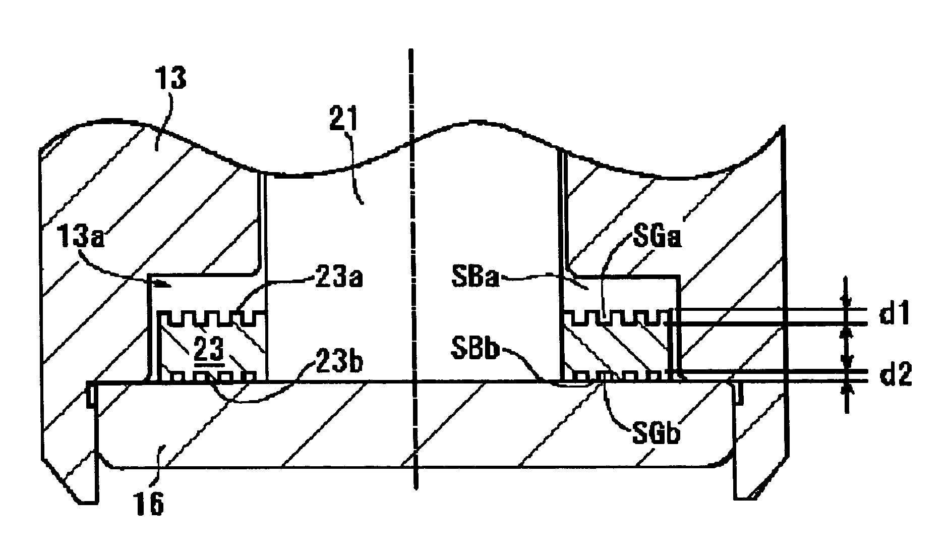
[0014]In this configuration, the shallower depth of the thrust dynamic pressure generating grooves generates larger dynamic pressure at a low speed of rotation. As a result, the rotating member is able to elevate from the fixed member in the thrust bearing portion even at a low speed of rotation such that the wearing of the contact sliding of both members is decreased. Accordingly, a fluid dynamic pressure bearing which is superior to its durability is obtained and a larger thrust dynamic pressure is obtained even in the thrust bearing portion in which the opposing gap space is small.
[0019]In this configuration, the thrust plate elevates from the side of the material of greater hardness and thus the wear of the thrust dynamic pressure bearing is restrained, regardless of the position of the motor in use, and the reliability of the bearing is improved.

Problems solved by technology

However, when the motor is placed in an upside down position or an extremely large shock is added to the motor from the outside, the rotating member becomes displaced to a larger extent than the elevated height and the hard disk may come into contact with the guide member, which damages the disk and / or the guide member.
However, the gap dimension between the magnetic plate and the motor drive magnet varies according to the assembling process of the motor or errors in the dimensions of various component parts.
Hence, the required thrust dynamic pressure may not be obtained.
In addition, when the gap space of the thrust dynamic pressure bearing is made smaller due to a stronger magnetic attraction force during rotation, the viscosity of the lubrication fluid increases and a loss of torque in the motor also increases.
That is, the time both members are in contact with each other increases and this causes the bearing to wear down.

Method used


Image

  • Fluid dynamic pressure bearing apparatus
  • Fluid dynamic pressure bearing apparatus
  • Fluid dynamic pressure bearing apparatus

Examples


Embodiment Construction

[0001]1. Field of the Invention

[0002]The present invention relates to a fluid dynamic pressure bearing apparatus and more particularly, to a fluid dynamic pressure bearing apparatus having a rotating shaft member and a bearing sleeve member wherein the rotating shaft member and the bearing sleeve member are supported in a relatively rotatable state by a dynamic pressure generated from a lubrication fluid disposed between a dynamic pressure surface of the rotating shaft member and a dynamic pressure surface of the bearing sleeve member.

[0003]2. Related Art

[0004]In recent years, various fluid bearing apparatuses have been proposed for rotatably supporting a rotator body such as magnetic disks, optical disks, or polygon mirrors in a high-speed rotation.

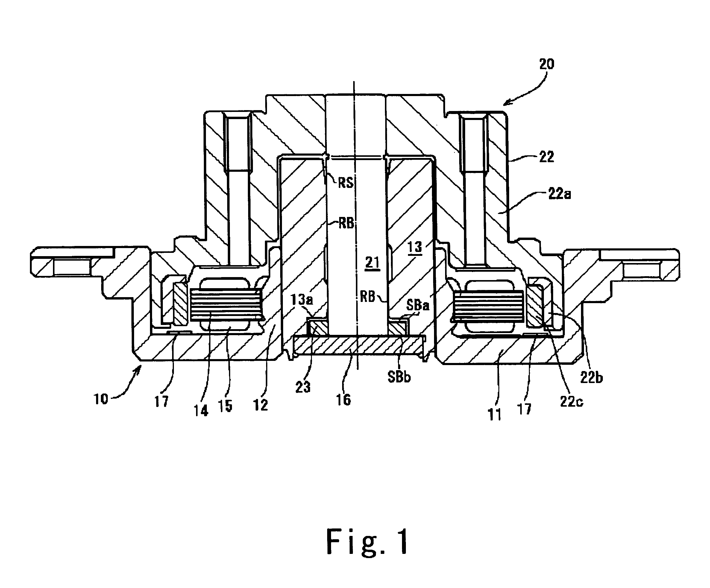
[0005]For example, a dynamic pressure bearing apparatus is used in a spindle motor such as a hard disk drive (HDD) shown in FIG. 7. A bearing sleeve 13 acts as a bearing member and is mounted for supporting a rotating shaft member 21. A ...


PUM

PropertyMeasurementUnit
depthaaaaaaaaaa
depthaaaaaaaaaa
depthaaaaaaaaaa

Abstract

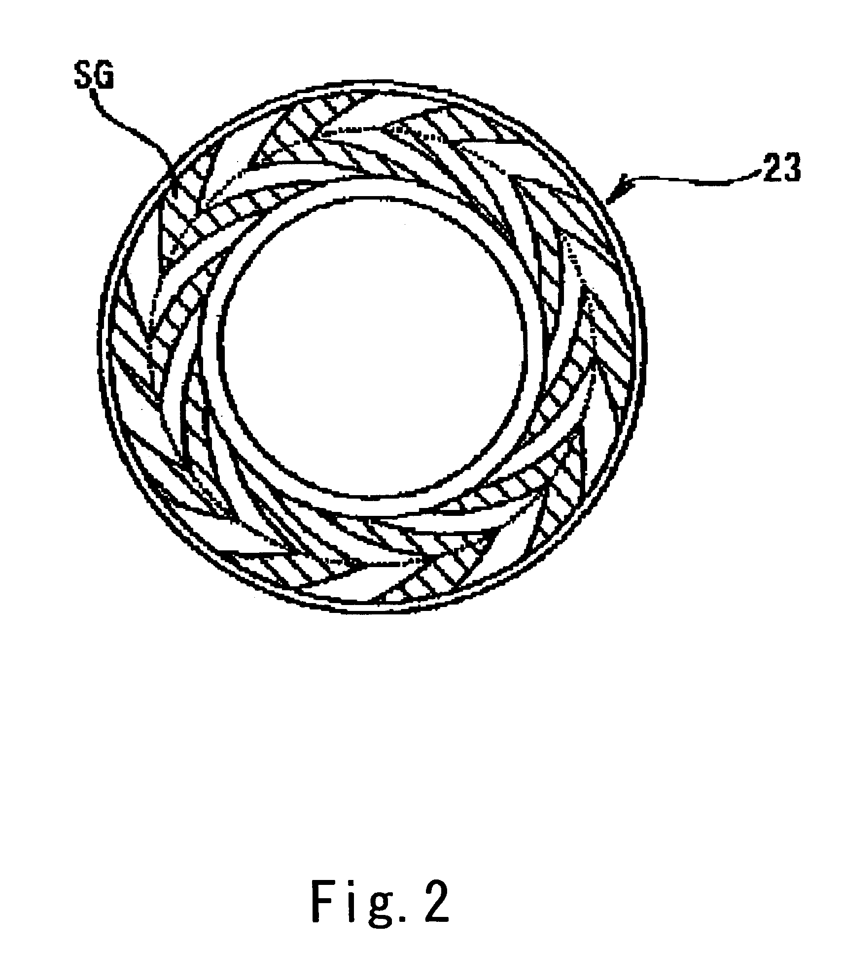
A fluid dynamic pressure bearing apparatus includes a radial dynamic pressure bearing formed in a gap portion between a bearing member and a shaft member. The apparatus also includes a thrust dynamic pressure bearing having a first thrust bearing portion formed between a top surface of the thrust plate and a first facing member opposing thereto in the axial direction and a second thrust bearing portion formed between a bottom surface of the thrust plate and a second facing member opposing thereto in an axial direction. Dynamic pressure generating grooves are formed on the radial dynamic pressure bearing and the thrust dynamic pressure bearing. The shaft member and the bearing member are rotated together as a rotation member, such that the rotation member is supported in a position such that a gap space L1 of the first thrust bearing portion is larger than a gap space L2 of the second thrust bearing portion and the depth of the dynamic pressure generating grooves where the gap space is smaller is formed shallower than that where the gap space is larger.

Description

DETAILED DESCRIPTION OF THE INVENTION[0001]1. Field of the Invention[0002]The present invention relates to a fluid dynamic pressure bearing apparatus and more particularly, to a fluid dynamic pressure bearing apparatus having a rotating shaft member and a bearing sleeve member wherein the rotating shaft member and the bearing sleeve member are supported in a relatively rotatable state by a dynamic pressure generated from a lubrication fluid disposed between a dynamic pressure surface of the rotating shaft member and a dynamic pressure surface of the bearing sleeve member.[0003]2. Related Art[0004]In recent years, various fluid bearing apparatuses have been proposed for rotatably supporting a rotator body such as magnetic disks, optical disks, or polygon mirrors in a high-speed rotation.[0005]For example, a dynamic pressure bearing apparatus is used in a spindle motor such as a hard disk drive (HDD) shown in FIG. 7. A bearing sleeve 13 acts as a bearing member and is mounted for supp...

Claims


Application Information

Patent Timeline
Patent Type & Authority Patents(United States)
IPC IPC(8): F16C33/04F16C33/10G11B19/20F16C17/10F16C33/12F16C39/06
CPCF16C17/045F16C17/10F16C33/107F16C39/063G11B19/2009F16C2240/40F16C2370/12F16C25/045
Inventor GOMYO, MASATO
Owner NIDEC CORP
Why Eureka
Eureka Blog
Learn More