
Method of forming box with gusseted corner

a box and corner technology, applied in the field of boxes, can solve the problems of increasing shipping costs, requiring more room for pre-assembled boxes, and content of boxes, and achieve the effects of saving shipping costs, simple design, and easy assembly

Inactive Publication Date: 2005-11-08
MALNOVE
View PDF7 Cites 15 Cited by
  • Summary
  • Abstract
  • Description
  • Claims
  • Application Information

AI Technical Summary

Benefits of technology

[0016]The box as thus described clearly offers several advantages over those devices found in the prior art. The relatively simple design and easy assembly of the present invention permits the box to be shipped to the end user in unassembled form, thus presenting a great savings in shipping costs. Also, because the box is constructed of thinner wall material than similar boxes currently on the market, the production costs of the box are substantially reduced. Furthermore, because the box includes gusseted corner construction, a plurality of boxes can be stacked with product therein to a greater height than that permitted by using prior art boxes. The present invention thus provides a substantial improvement over those devices found in the prior art.

Problems solved by technology

Of course, however, a wall which is too thin will not permit stacking of assembled boxes atop one another or can provide insufficient protection for the contents of the box, which is undesirable.
As the increased thickness is not a viable option, it then becomes imperative to design a box which includes reinforced wall, particularly corner, construction.
The transport of pre-assembled boxes results in greatly increased shipping costs, as much of the shipping space is taken up by the interior volume of the assembled boxes.
Also, the storage of preassembled boxes requires greater room, which many businesses cannot allocate without sacrificing space which is sorely needed for business operations.

Method used


Image

  • Method of forming box with gusseted corner
  • Method of forming box with gusseted corner
  • Method of forming box with gusseted corner

Examples


Embodiment Construction

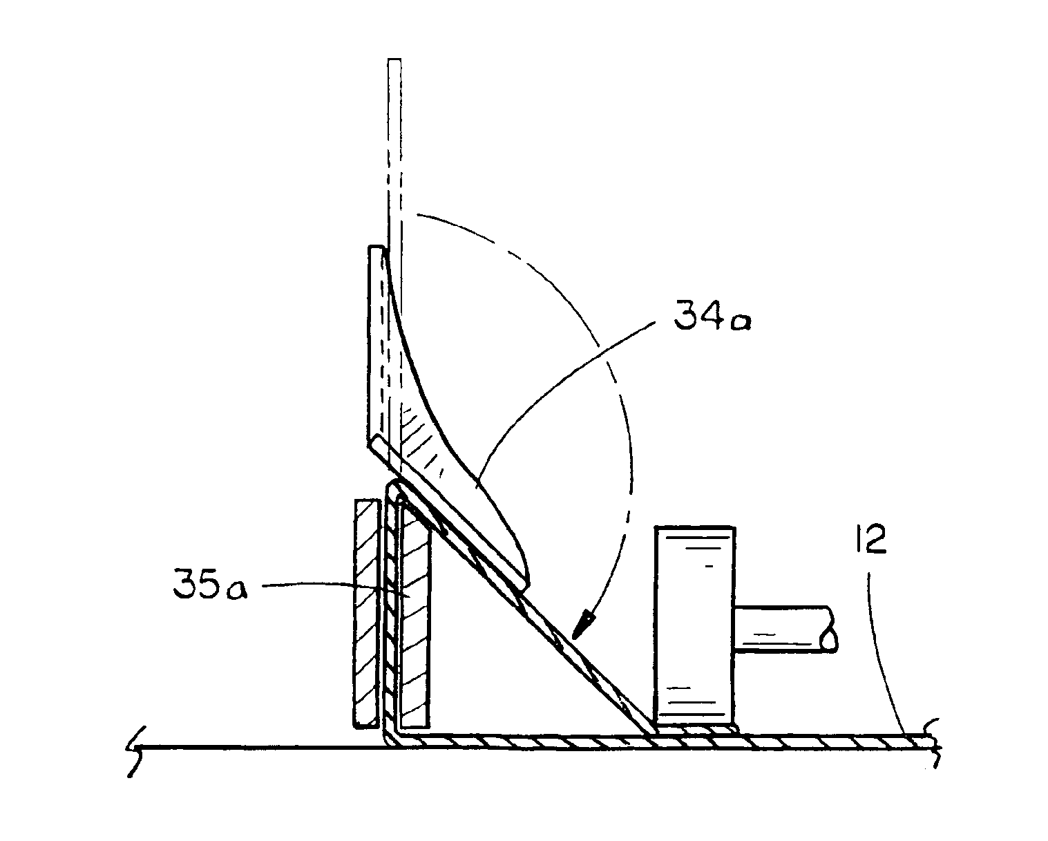
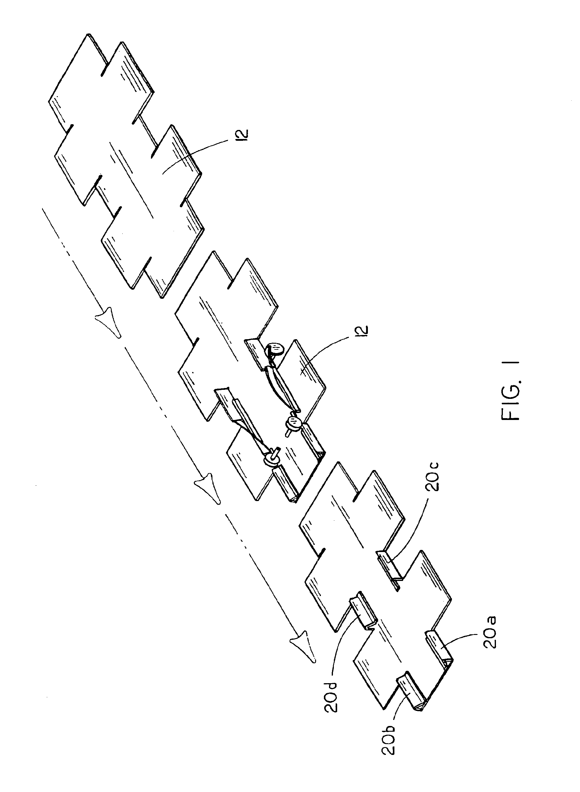
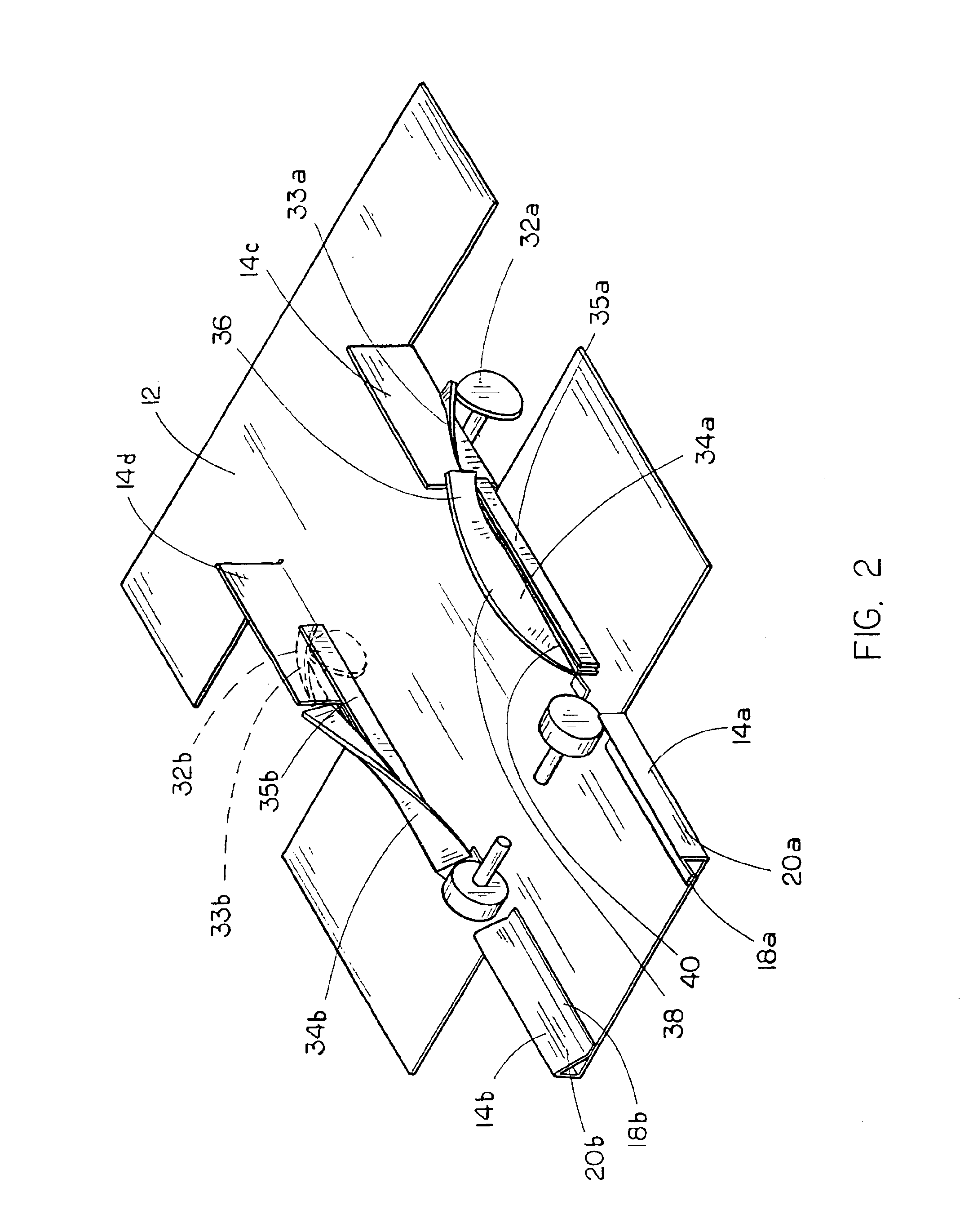
[0021]The box with gusseted corners 10 of the present invention is shown best in FIGS. 1-4b as being constructed from a single flat blank 12 which, when assembled, forms the box with gusseted corners 10. In the preferred embodiment, flat blank 12 would be placed on a feed conveyor (not shown) and be fed into the gusset construction section of the box assembly line. As shown best in FIGS. 1 and 2, the gusset assembly section 30 would include a pair of rotatably mounted kicker wheels 32a and 32b which are mounted adjacent to and parallel with the direction of travel of the blank 12, the kicker wheels 32a and 32b operative to deform the gusset corner formation sections 14a, 14b, 14c, 14d of the blank 12 upwards to a generally upright position as shown best in FIG. 2. As the blank 12 is moved forwards on the conveyer belt, the kicker wheels 32a and 32b alternatively rotate to move kicker plates 33a and 33b into forming position wherein the gusset corner formation sections 14a-d are tilt...


PUM


Abstract

A method of forming a box having a plurality of corner gussets includes the steps of providing a generally planar box blank and a box forming device including a gusset formation section having a kicker plate, a forming blade and an adhesive securement device. The box blank is fed into the box forming device, the kicker plate deflects each of the gusset corner formation wall sections upwards, the upper portion thereof is bent towards a side wall via the forming blade and the glue flap section is secured to the side wall via the adhesive securement device to form a gusset, and the box is formed by folding the side walls upwards generally perpendicular to the base wall and securing adjacent ones of the side walls to one another whereby the box is formed. A box formed via the above-described method is also claimed.

Description

CROSS-REFERENCE TO RELATED UTILITY AND PROVISIONAL PATENTS[0001]This continuation application claims priority based on previously filed provisional and utility patents, specifically on the provisional patent application Ser. No. 60 / 327,523 filed Oct. 5, 2001 and to utility patent application Ser. No. 10 / 264,652 filed Oct. 5, 2002, now abandoned.BACKGROUND OF THE INVENTION[0002]1. Technical Field[0003]The present invention relates to boxes having reinforced corner structures and, more particularly, to a generally rectangular box having gusseted corner construction and a method of forming the same in which the box is formed from a single blank on which the gusset corners are formed, the box then being assembled to provide for storage of materials therein and a method of forming the same which includes construction of the gusseted corners prior to assembly of the box.[0004]2. Description of the Prior Art[0005]In the field of paper box design and construction, there are several differen...

Claims


Application Information

Patent Timeline
Patent Type & Authority Patents(United States)
IPC IPC(8): B65D5/00
CPCB65D5/002B31B50/36B31B2120/502
Inventor DALRYMPLE, BRUCE H.
Owner MALNOVE
Learn More