Ground rod

a ground rod and rod body technology, applied in the field of ground rods, can solve the problems of constant electrocution risk of utility workers, difficulty and time-consuming, and truck hitting a hot wire, and achieve the effect of convenient installation

Inactive Publication Date: 2005-11-08
BRENNAN BOB
View PDF14 Cites 19 Cited by
  • Summary
  • Abstract
  • Description
  • Claims
  • Application Information

AI Technical Summary

Benefits of technology

[0007]Accordingly, it is the object of the present invention to provide a ground rod that is easy to install.

Problems solved by technology

Utility workers constantly face the risk of electrocution when working with high voltage electric wires.
When using a lift truck there is also the possibility that the truck will strik

Method used


Image

  • Ground rod
  • Ground rod
  • Ground rod

Examples


Embodiment Construction

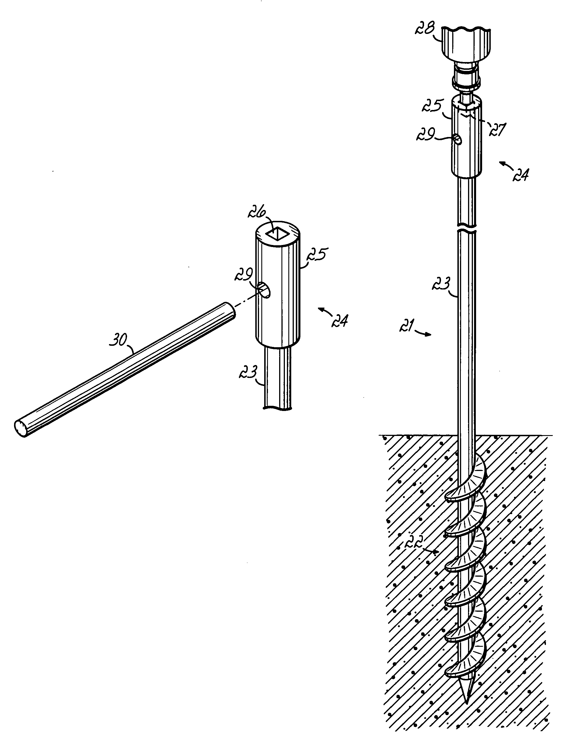
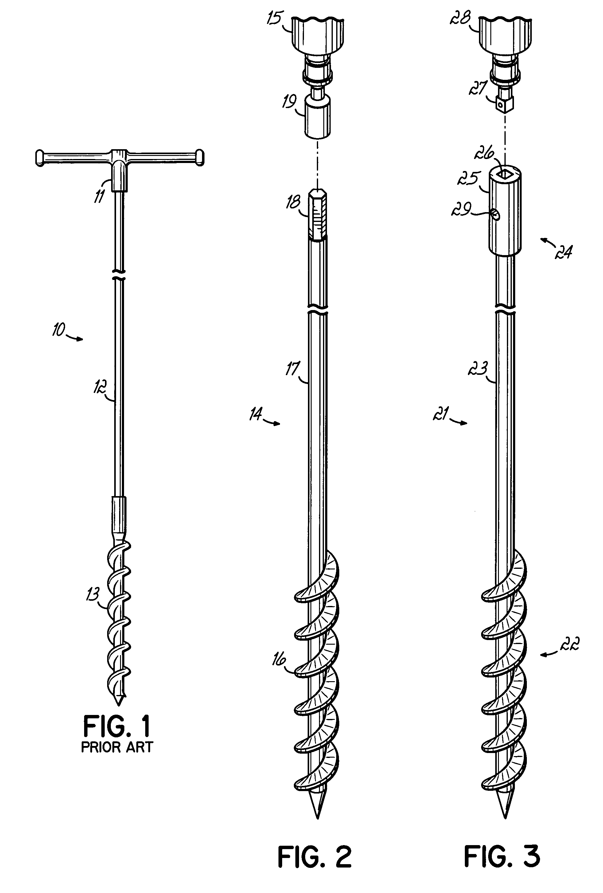
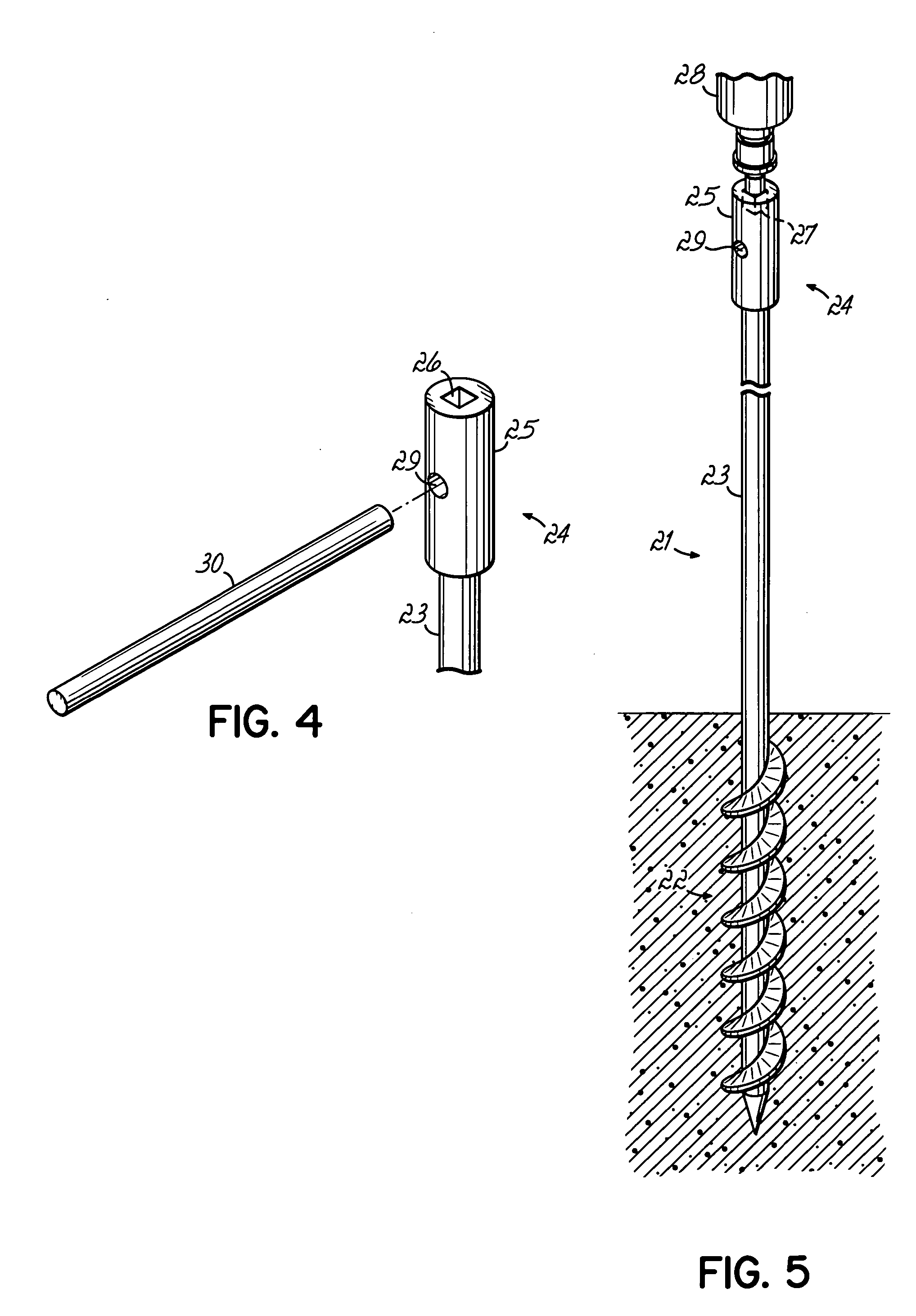
[0016]As shown in FIG. 2, the present invention is a ground rod 14 which is adapted to be driven into the ground by an electric drill 15 or an impact wrench. The ground rod 14 includes an auger tip section 16, a shaft section 17 and a head 18 which is adapted to mate with a drill. The end 19 can be adapted to mate with an electric drill or impact srench in a number of ways. The head can simply be faceted like the end of a drill bit. This will allow the chuck of the drill bit to grasp the head. The head can be enlarged and faceted, like the head of a bolt. This will allow a socket to mate with and engage the head. The socket would be driven by a quarter, half or three quarter inch standard drive which would be held in the drill's chuck or by the impact wrench. The head can also be enlarged and have a square recess adapted to receive the socket drive directly, as shown in FIG. 4.

[0017]Generally, the ground rod 14 is made from a conductive material, in particular copper clad steel. The...


PUM


Abstract

A ground rod includes first and second ends connected by a shaft portion. The first end has an auger configuration permitting it to be drilled into the ground. The opposite end is adapted to attached to either an electric drill or an impact wrench. This drastically reduces the time required to drive the ground rod into the ground. In an alternate embodiment, the ground rod also adapted to attach to a handle which allows it to be manually inserted or removed from the ground.

Description

[0001]This application claims benefit of Provisional application Ser. No. 60 / 445,955, filed Feb. 7, 2003.BACKGROUND[0002]Ground rods are used in a variety of situations for safety. Ground rods are attached to the electrical system of a building to prevent electrical shock of equipment or individuals.[0003]Utility workers constantly face the risk of electrocution when working with high voltage electric wires. When using a lift truck there is also the possibility that the truck will strike a hot wire. To reduce these risks, the truck should be grounded. Some locations have permanent grounds to which the truck can attach. However, in many locations there are no such grounds. Therefore, the electrical worker, in order to ensure safety, should install a temporary ground rod and connect the truck to the ground rod.[0004]To be effective, the ground rod must be inserted a minimum distance into the ground usually about six feet. This will assure adequate contact with moist dirt and allow for...

Claims


Application Information

Patent Timeline
IPC IPC(8): H01R4/66
CPCH01R4/66
Inventor BRENNAN, BOB
Owner BRENNAN BOB
Why Eureka
Try Eureka