Electromagnetic coupler system

a technology of electromagnetic couplers and couplers, applied in the field of communication, to achieve the effect of simplifying and optimizing the operation of such couplers

Inactive Publication Date: 2005-11-08
KNAPP GUENTHER
View PDF8 Cites 45 Cited by
  • Summary
  • Abstract
  • Description
  • Claims
  • Application Information

AI Technical Summary

Benefits of technology

[0006]Improvements simplify and optimize the operation of such couplers with regard to wall material, installation, privacy and low RF power requirement.

Problems solved by technology

The remaining problem is to provide information transfer also with bidirectional signal flow for accommodation of communication networks that do not have a ring, star or similar structure.

Method used


Image

  • Electromagnetic coupler system
  • Electromagnetic coupler system
  • Electromagnetic coupler system

Examples


Embodiment Construction

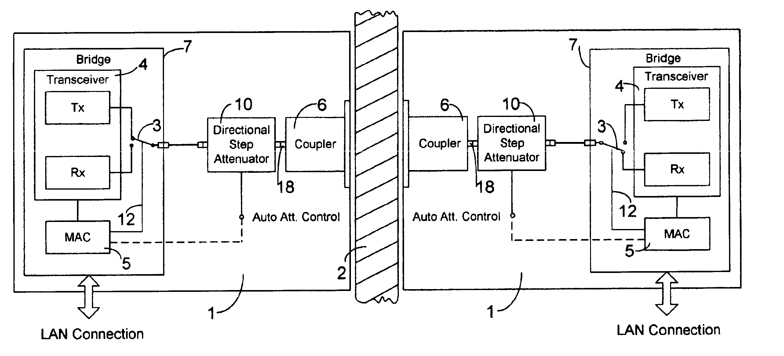
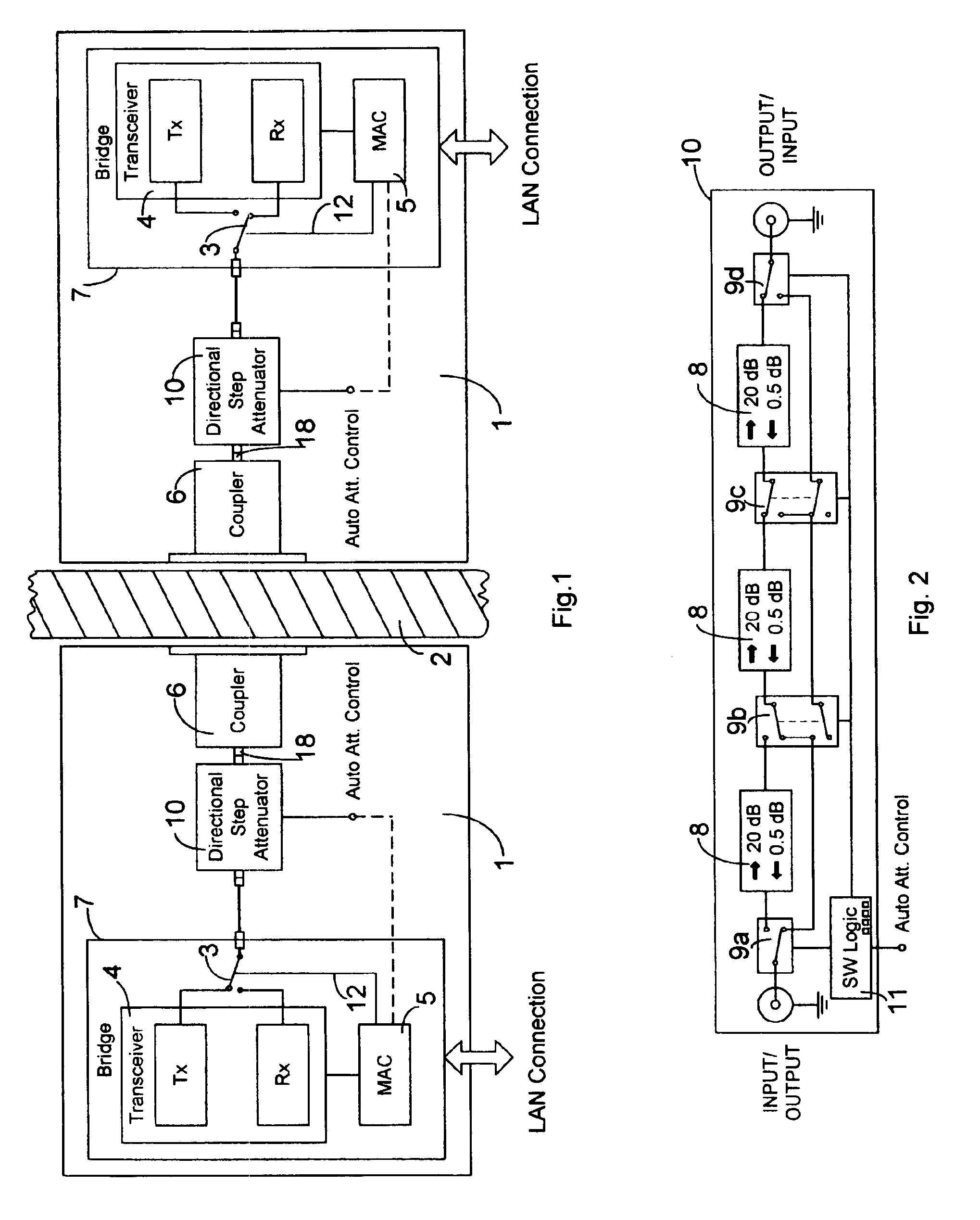
[0013]In accordance with the present invention, system 1 communicates through a nonmetallic barrier such as a concrete wall or ceiling 2. The block diagram FIG. 1 depicts two electromagnetic wall coupler systems 1 for a wired LAN, operating with a protocol that requires bidirectional signal flow. The direction of signal flow for the transceiver 4 is set by Tx / Rx switch 3 with control line 12 in accordance to a communication protocol. For example, operation with an Ethernet's CSMA (Carrier-sense-multiple-access) protocol directing a MAC (media access control) system 5 when to transmit (Tx) and when to receive (Rx). Conventional MAC controlled transceivers for the purpose of wireless connection of two wired LAN segments are known as wireless bridges. In FIG. 1, two are depicted as bridge 7. Wireless bridge designs vary with the bridged media: wire / RF to RF / wire, fiber / RF to RF / fiber or RF / RF to RF / RF. They are all suitable for operating the bidirectional electromagnetic couplers 6 if ...


PUM


Abstract

This invention makes it possible to communicate through solid non-metallic walls or ceilings with low microwave power levels. RF beam forming couplers are driven by common networks.For connection to a LAN segment at the other side of a wall or ceiling, transceiver 4 transmits data modulated microwave RF to coupler 6 through a directional step attenuator 10. The reduced signal is received by the coupler system at the other side with a power level low enough to eliminate wireless detection from the outside. However, the directional step attenuator on the receive side reduces the signal power only by an insignificant amount due to its low directional losses during receive signal flow. Each coupler's geometry is minimizing the radiation exposed material volume by RF field concentration, therefore, enabling transmission through thick concrete walls at microwave frequencies without compromising privacy. When used as wireless access point, coupler transmits through a floor to wireless devices below. The preferred embodiment operates in the 5-GHz ISM band.

Description

FIELD OF INVENTION[0001]This invention is related to the field of communication where information is sent through non-metallic walls and ceilings by wired LANs (Local Area Networks) or wireless communication networks with signals strongly attenuated or blocked by thick walls and ceilings.DESCRIPTION OF PRIOR ART[0002]U.S. Pat. No. 5,218,356 issued to G. Knapp on Jun. 8, 1993 describes within a wireless network a device capable of transmitting data through a non-metallic wall or ceiling that otherwise would be blocked or unduly attenuated because of the high electromagnetic frequency employed in broadcasting or line-of-sight operation of a LAN. The described structure coupler has an independent transmission path for outbound data and an independent transmission path for inbound data.[0003]Knapp's patent has on each side of a wall or ceiling one infrared (IR) transmitter, one IR receiver, one radio frequency (RF) transmitter, one RF receiver, and two RF antennas. In addition, there is...

Claims


Application Information

Patent Timeline
Patent Type & Authority Patents(United States)
IPC IPC(8): H01Q1/12H04L12/28
CPCH01Q1/1285H04W92/02H04W84/12H04W52/0206Y02B60/50Y02D30/70
Inventor KNAPP, GUENTHER
Owner KNAPP GUENTHER
Why Eureka
Try Eureka