

Signal line driving circuit and light emitting device
- Summary
- Abstract
- Description
- Claims
- Application Information
AI Technical Summary
Benefits of technology
Problems solved by technology
Method used
Image

Examples
first embodiment
[First Embodiment]
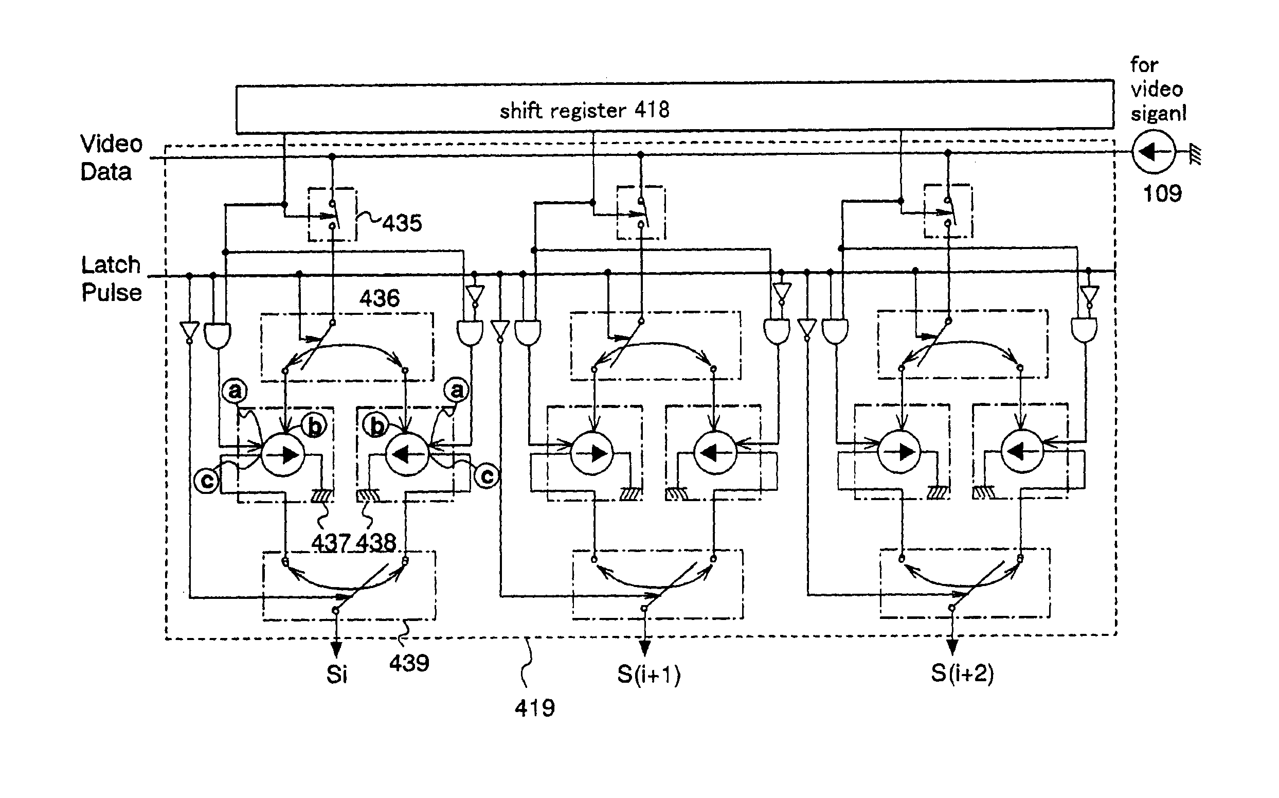
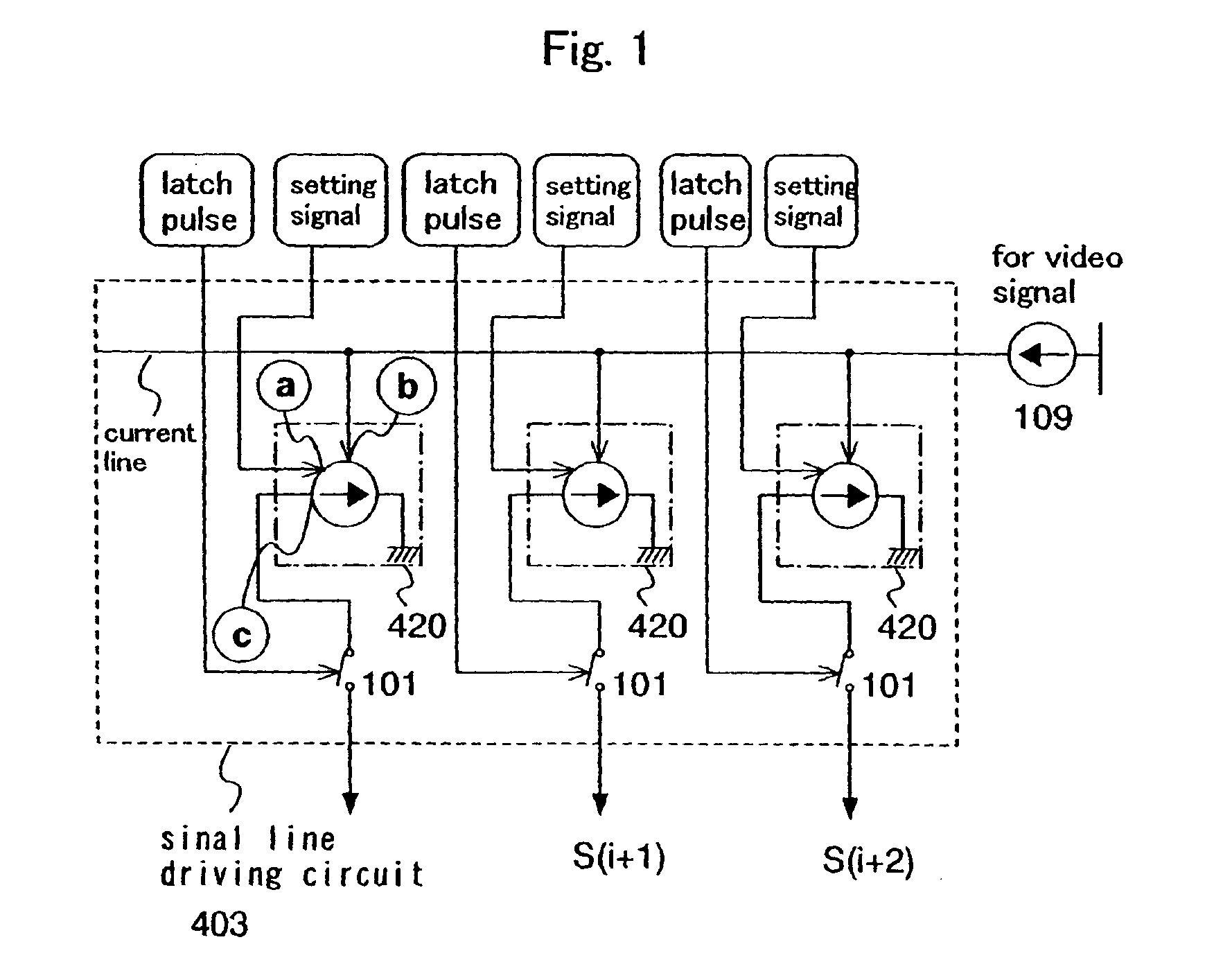
[0101]In this embodiment, an example of a circuit structure and its operation of a current source circuit 420 which is supplied in a signal line drive circuit of the present invention will be described.
[0102]In the invention, a setting signal input from a terminal a represents a signal input from an output terminal of a logical operator. In other words, the setting signal in FIG. 1 corresponds to the signal input from the output terminal of the logical operator. In the present invention, the setting operation of the current source circuit 420 is performed in accordance with the signal input from the output terminal of the logical operator.
[0103]One of two input terminals of the logical operator is input with a sampling pulse from a register, and the other is input with a latch pulse. In the logical operator, a logic operation of two signals which have been input is performed, and a signal from the output terminal is output. Then in the current source circuit, the s...
second embodiment
[Second Embodiment]
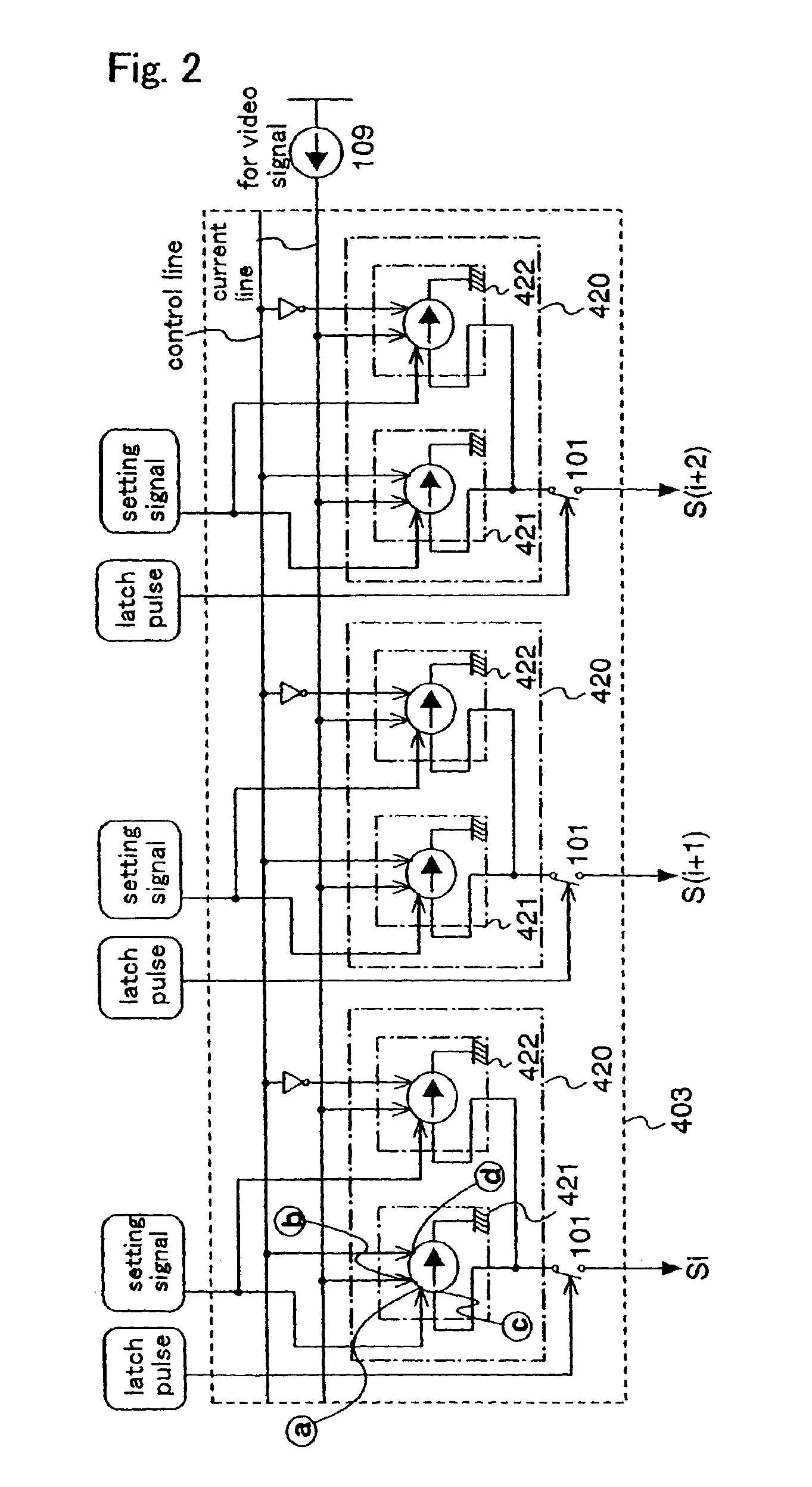
[0175]The above has described that, for a current source circuit like the one shown in FIG. 6 (and, FIGS. 19, 31A, 6B, 29B, or the like), preferably, two current source circuits are provided for each signal line (each column), in which one of the current source circuits is used to perform the signal setting operation (set operation), and the other current source circuit is used to perform the Idata input operation (input operation) to the pixel. This is because the setting operation and the input operation cannot be performed simultaneously. In this embodiment, an exemplary circuit structure of the current source circuit 420 shown in FIG. 2, which has a signal drive circuit of the present invention, will be described with reference to FIG. 8.
[0176]In the present invention, a setting signal input from a terminal a represents a signal input from an output terminal of a logical operator. In other words, the setting signal in FIG. 1 corresponds to the signal input fro...
third embodiment
[Third Embodiment]
[0190]In this embodiment, the structure of a light emitting device including the signal line drive circuit of the present invention will be described using FIG. 15.
[0191]The light emitting device includes a pixel portion 402 including a plurality of pixels arranged in matrix on a substrate 401, and includes a signal line drive circuit 403 and a first scanning line drive circuit 404 and a second scanning line drive circuit 405 in the periphery of the pixel portion 402. While the signal line drive circuit 403 and the two scanning line drive circuits 404 and 405 are provided in FIG. 15A, the present invention is not limited to this. The number of drive circuits may be arbitrarily designed depending on the pixel structure. Signals are supplied from the outside to the signal line drive circuit 403, the first scanning line drive circuit 404 and the second scanning line drive circuit 405 via FPCs 406.
[0192]The structures and operations of the first scanning line drive cir...
PUM
 Abstract
Description
Claims
Application Information