Liquid ejecting recording head and liquid ejecting recording apparatus

a recording head and liquid ejection technology, applied in the direction of printing, spacing mechanisms, inking apparatus, etc., can solve the problems of affecting the quality of liquid ejection, and causing color anomalies in the form of stripes, etc., to achieve the effect of reducing the recording head size, high resolution and easy printing

Inactive Publication Date: 2005-11-15
CANON KK
View PDF22 Cites 35 Cited by
  • Summary
  • Abstract
  • Description
  • Claims
  • Application Information

AI Technical Summary

Benefits of technology

[0026]As described above, according to the present invention, a color image with a desired high level of resolution can be produced simply by adjusting the positional relationship between the first and second groups of ejection orifices. Further, the first and second groups of ejection orifices can be placed adjacent to each other in such a manner that the ejection orifice column in the first ejection orifice group, which ejects the first liquid, and the ejection orifice column in the second ejection orifice group, which also eject the first liquid, are placed adjacent to each other, making it possible to make these two columns of ejection orifices share the same liquid path. Consequently, recording head size can be reduced in both the primary and secondary scanning directions, and it becomes easy to print at high speed, without causing unevenness in color, even in bidirectional printing.

Problems solved by technology

However, bidirectional printing suffers from an inherent problem.
That is, it is liable to produce color anomaly in the form of stripes.
Since this problem is caused by the order in which inks are applied, overlapping of dots different in color results in a certain amount of color aberration, no matter how small the amount of the overlapping.
However, a structure such as the one disclosed in Japanese Laid-Open Patent Application 1-208,143 / 1989 makes a recording head relatively long compared to the size of the recording area covered by each color, creating a problem in that this structure makes apparatus dimension relatively large in terms of the secondary scanning direction.
On the other hand, a structure such as the one disclosed in Japanese Laid-Open Patent Applications 58-208143 / 1983 and 58-215352 / 1983 increases head size in the primary scanning direction, creating a problem in that this structure makes apparatus dimension increases in terms of the primary scanning direction.
Increase of recording head size in the primary scanning direction results in increase in scanning time, being undesirable from the standpoint of high speed recording.
A structure such as the one disclosed in Japanese Laid-Open Patent Application 58-215,352 / 1983 causes head misalignment relative to each other when a plurality of heads are combined to form a recording head portion; in other words, it is liable to cause production errors.
Assembling this type of recording head portion is liable to make the structure for aligning the plurality of recording heads complicated, as well as to increase the size of such a structure.

Method used


Image

  • Liquid ejecting recording head and liquid ejecting recording apparatus
  • Liquid ejecting recording head and liquid ejecting recording apparatus
  • Liquid ejecting recording head and liquid ejecting recording apparatus

Examples


embodiment 1

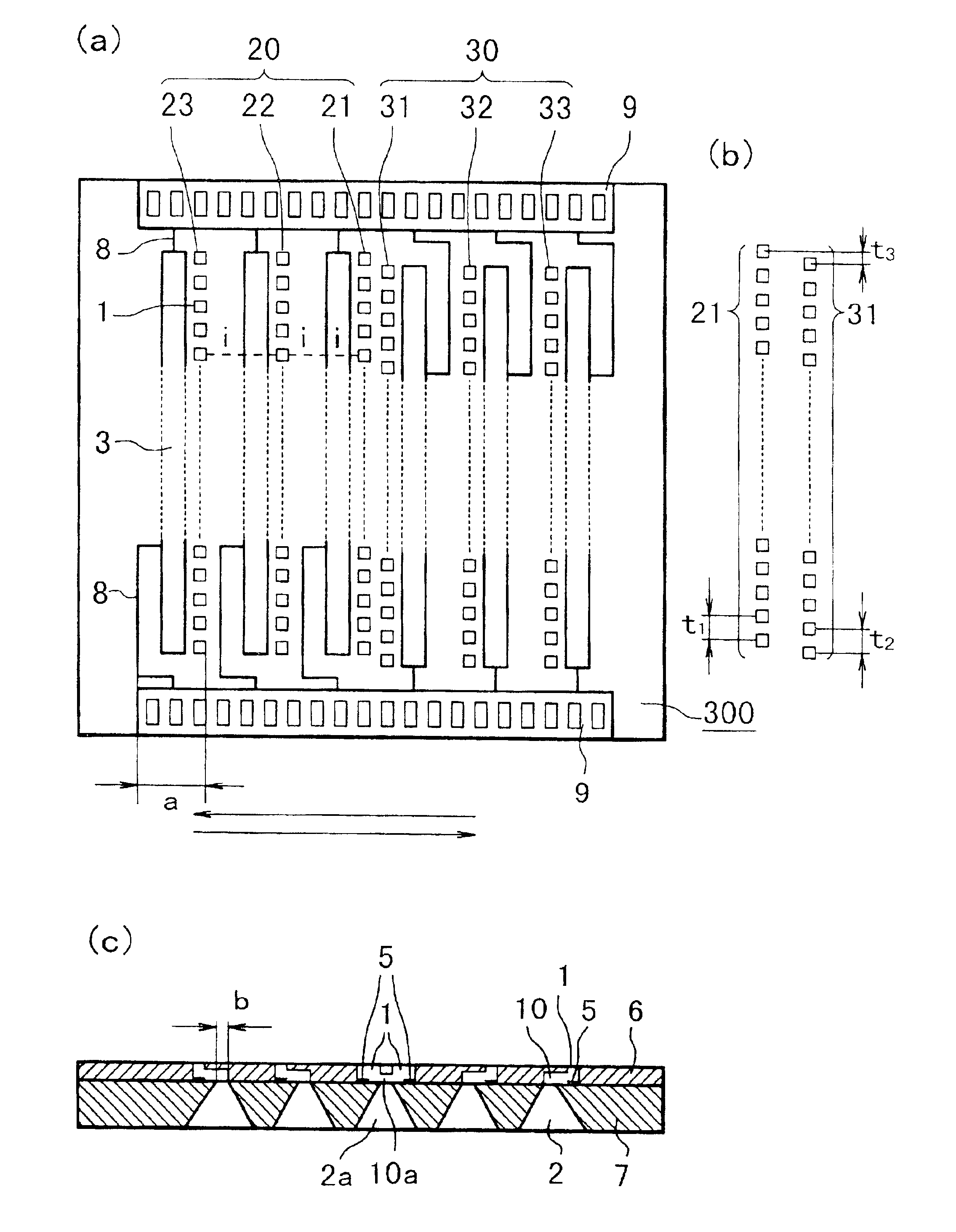
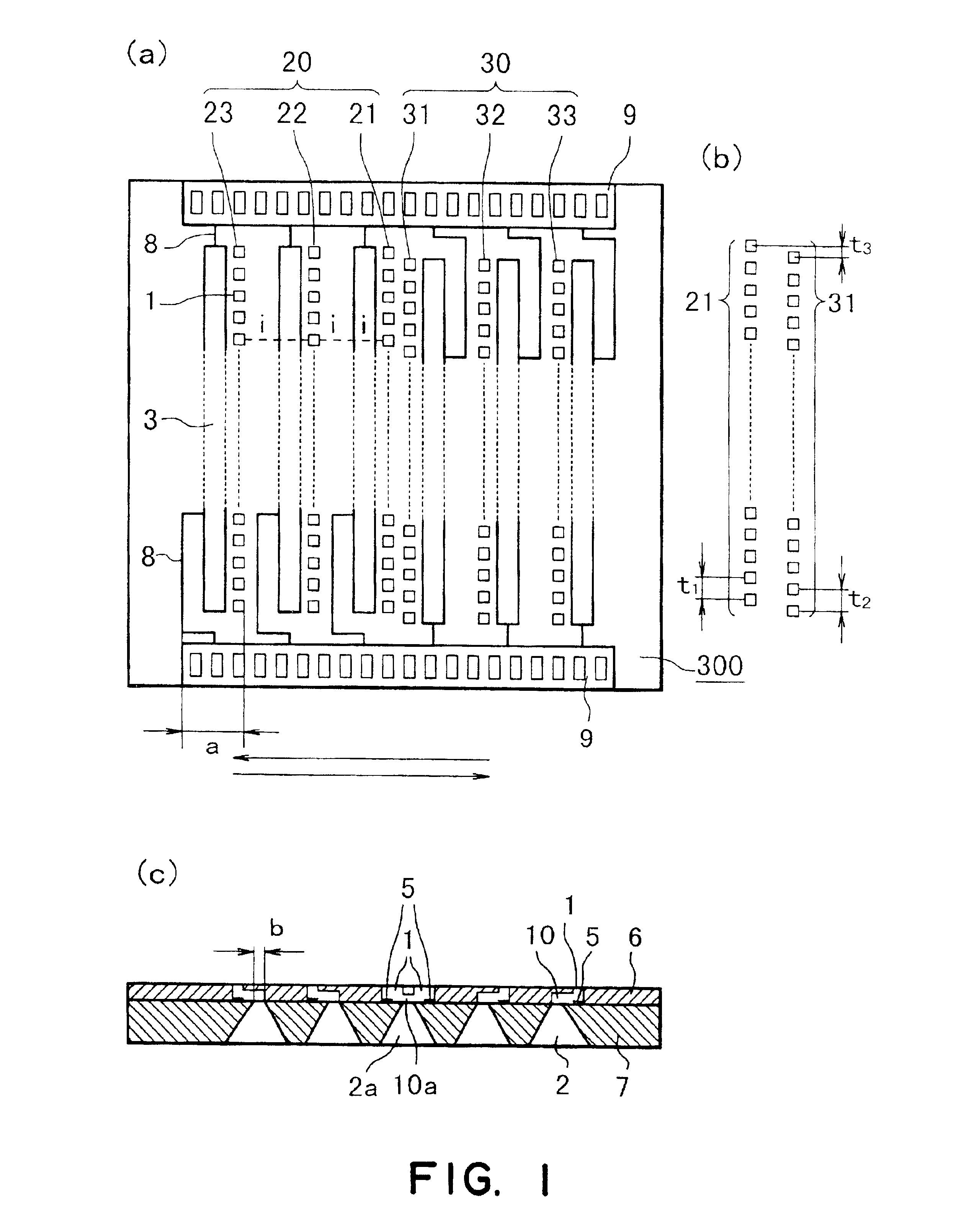
[0039]FIG. 1 is a schematic drawing which shows the essential portion of the recording head in the first embodiment of the present invention. FIG. 1(a) is a top view, and FIG. 1(b) is a schematic drawing for describing the positioning of the ejection orifices. FIG. 1(c) is a sectional drawing. As is shown in FIG. 1(c), a recording head 300 in this embodiment comprises a substrate 7 inclusive of exothermal elements 5 as energy transducers, and an orifice plate 6 which has ejection orifices 1.

[0040]In this embodiment, the substrate 7 is formed of a single crystal with a crystal face orientation of . Referring to FIG. 1(a), the top surface (surface which joins the surface of the orifice plate 6) of this substrate 7 has exothermic elements 5, a driver circuit 3 comprising driver transistors and the like for driving these exothermic elements 5, a contact pad 9 for a wiring plate, which will be described later, wires 8 and the like which connect the driver circuit 3 and contact pad 9, and...

embodiment 2

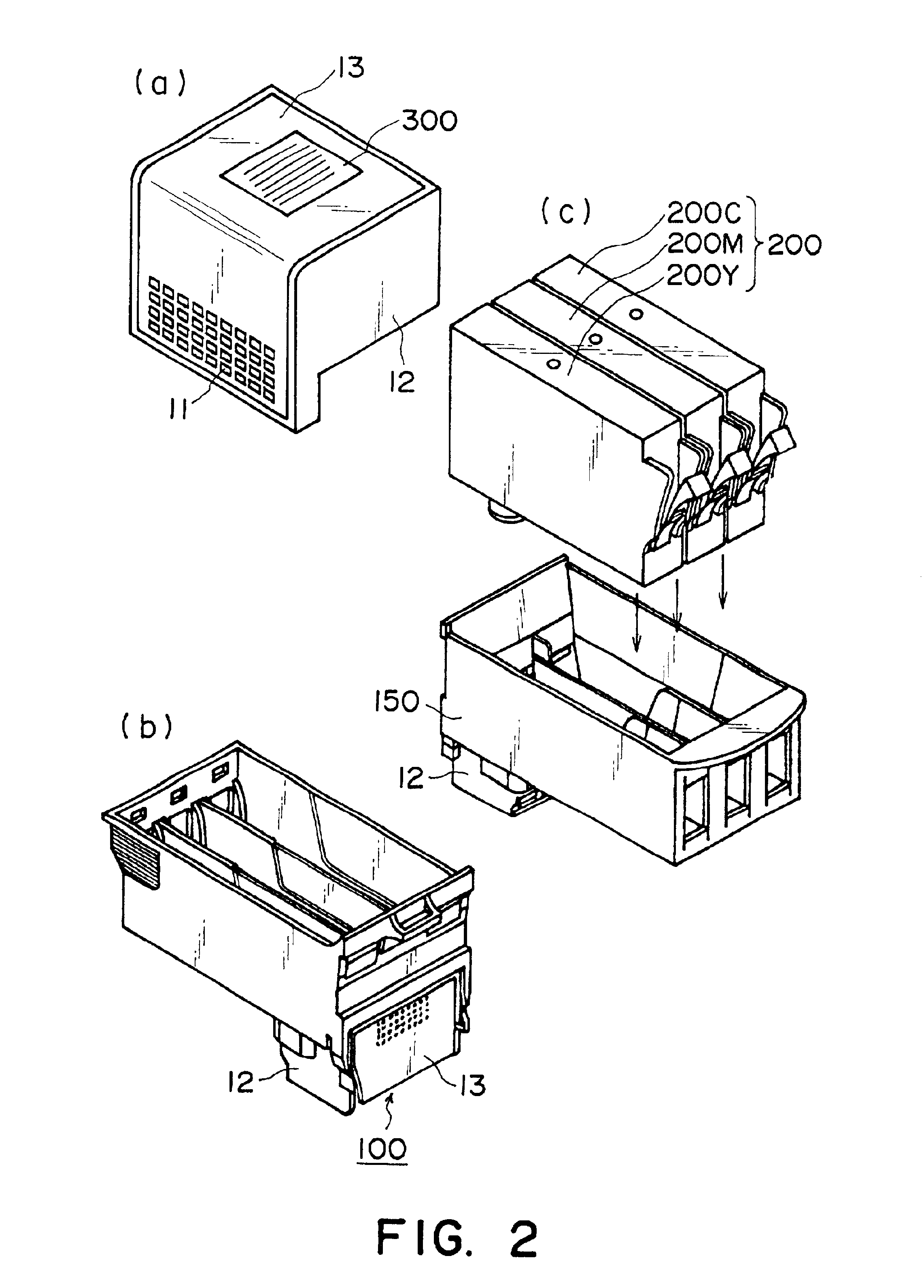
[0059]FIGS. 3 and 4 are drawings which show the recording head in the second embodiment of the present invention, and a recording head cartridge in which this recording head is mounted. In the drawings, the components and portions which are the same in function as those in the first embodiment are given the same referential codes as those in the first embodiment, and their detailed descriptions will be not be given. FIG. 3 is a schematic drawing which depicts the essential portion of the recording head. FIG. 3(a) is a schematic drawing as seen from the top, and FIG. 3(b) is a schematic drawing which depicts the positioning of the ejection orifices. FIG. 3(c) is a sectional view. FIG. 4(a) is a perspective view of the recording head illustrated in FIG. 3, which is fixed to an ink path member 12, and FIG. 4(b) is a perspective view of an example of a recording head cartridge 100 equipped with the recording head 300 in accordance with the present invention. FIG. 4(c) is a perspective v...

embodiment 3

[0063]FIG. 5 is a drawing which shows the recording head in the third embodiment of the present invention. In this drawing, the components and portions which are the same in function as those in the first and second embodiments are given the same referential codes as those in the first and second embodiments, and their detailed descriptions will be not be given. FIG. 5 is a schematic drawing which depicts the essential portion of the recording head. FIG. 5(a) is a schematic drawing as seen from the top, and FIG. 5(b) is a schematic drawing which depicts the positioning of the ejection orifices. FIG. 5(c) is a sectional view.

[0064]This embodiment is different from the first and second embodiments in that the number of through holes provided in the substrate 7 is three. The ink supplying holes 2b correspondent to the two outermost ejection orifice columns are formed by the edge portions of the substrate 7 and the ink path member 12. With this arrangement, it is possible to further red...


PUM


Abstract

A liquid ejection recording head for effecting recording by ejecting first liquid and second liquid which is a different kind of liquid through different ejection outlets, while bi-directionally scanning a recording material in a scanning direction includes a group of first ejection outlet arrays each of which has a plurality of ejection outlets at predetermined intervals arranged in a direction different from the scanning direction, wherein corresponding ejection outlets in the respective ejection arrays are aligned in the scanning direction; a group, disposed adjacent the group of the first ejection outlet arrays, of second ejection outlet arrays arranged in a manner similar to the first ejection outlet array group; wherein the first ejection outlet arrays include a first ejection outlet array for ejecting the first liquid and a second ejection outlet array for ejecting the second liquid; wherein the second ejection outlet arrays include a third ejection outlet array for ejecting the first liquid and a fourth ejection outlet array for ejecting the second liquid; wherein the first ejection outlet array group and the second ejection outlet array group are disposed such that first ejection outlet array and third ejection outlet array are adjacent to each other and that ejection outlets of the first ejection outlet array and the ejection outlets of the third ejection outlet array are disposed with deviation in a direction of arrangement of the ejection outlets so as to be complementary to each other in the scanning direction.

Description

FIELD OF THE INVENTION AND RELATED ART[0001]The present invention relates to a liquid ejecting recording head and a liquid ejection recording apparatus, which apply various liquids, for example, inks different in color, to recording media, for example, a sheet of paper. In particular, it relates to a liquid ejecting recording head and a liquid ejecting recording apparatus, which are employed by a bidirectional printing apparatus, that is, a printing apparatus capable of recording in either the forward or backward direction by moving a recording head in a manner to scan a piece of recording medium.[0002]In the field of a printing apparatus, in particular, an ink jet type printing apparatus, improvement in recording speed in color mode is an essential theme. As means for improving recording speed, increasing the frequency with which a recording head is driven, and bidirectional printing, are generally considered, in addition to lengthening a recording head. In bidirectional printing, ...

Claims


Application Information

Patent Timeline
Patent Type & Authority Patents(United States)
IPC IPC(8): B41J2/14B41J19/14B41J19/00B41J2/05B41J2/00
CPCB41J2/1404B41J19/147B41J2002/14387B41J2002/14475B41J2202/11B41J2/00
Inventor KANEKO, MINEOOTSUKA, NAOJI
Owner CANON KK
Why Eureka
Try Eureka