

Temperature determining device, temperature correcting method, and image forming apparatus
a technology of temperature determining device and temperature correction method, which is applied in the direction of heat measurement, optical radiation measurement, instruments, etc., to achieve the effect of high-quality image and stable results
- Summary
- Abstract
- Description
- Claims
- Application Information
AI Technical Summary
Benefits of technology
Problems solved by technology
Method used
Image

Examples
embodiment 1
[0042](Embodiment 1)
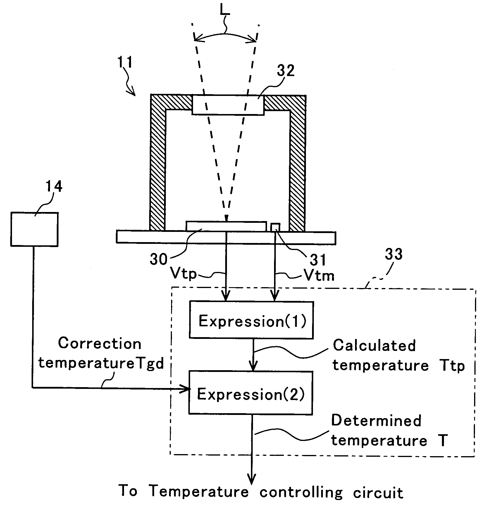
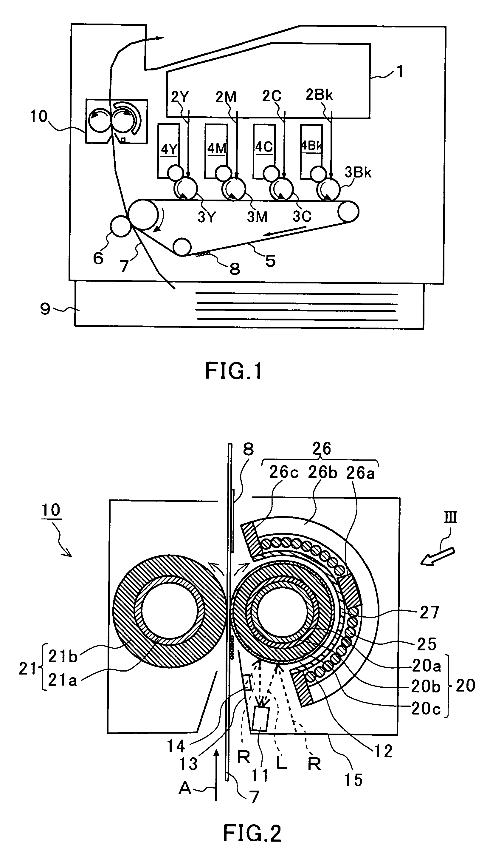
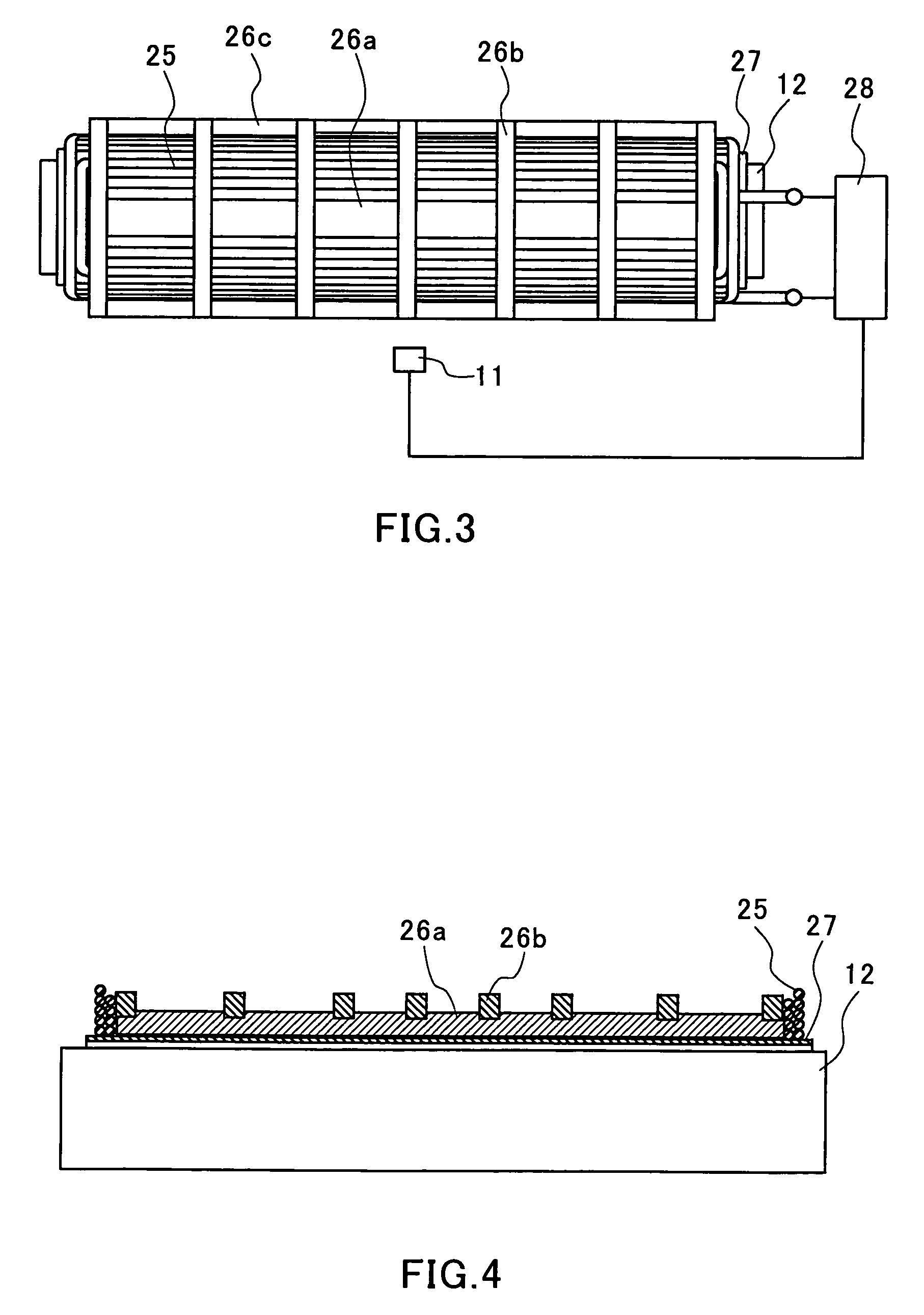
[0043]FIG. 1 is a cross sectional view of an image forming apparatus according to Embodiment 1 of the present invention. FIG. 2 is an expanded sectional view of a fixer 10. FIG. 3 is a perspective view of a heating source including an excitation coil 25 as seen from a direction indicated by an arrow III shown in FIG. 2. FIG. 4 is a cross sectional view taken along a width direction (longitudinal direction) of the heating source including the excitation coil 25. FIG. 5 is a diagram for explaining an induction heating action of the heating source. FIG. 6 is structural view of a temperature sensor 11.
[0044]In FIG. 1, reference numeral 1 denotes an exposure device that outputs four laser beams 2Y, 2M, 2C and 2Bk corresponding respectively to image signals. Reference numerals 3Y, 3M, 3C and 3Bk denote photosensitive bodies on which latent images are formed by the laser beams 2Y, 2M, 2C and 2Bk, respectively. Reference numerals 4Y, 4M, 4C and 4Bk denote developers that...
embodiment 2
[0086](Embodiment 2)
[0087]The only difference between Embodiment 2 and Embodiment 1 lies in the following point. That is, as the temperature for correction, while the temperature of the paper guide 13 obtained by the correction temperature sensor 14 was used in Embodiment 1, a temperature Ttm obtained from a thermistor 31 for compensating for the temperature of a cold junction of a thermopile 30 is used in Embodiment 2. The following description is directed to the difference of Embodiment 2 from Embodiment 1.
[0088]In this embodiment, in place of the expression (2) described with regard to Embodiment 1, the following expression (3) is used to correct a calculated temperature Ttp so as to obtain a determined temperature Tfb.
Tfb=Ttp×(A2×Ttm2B2×Ttm+C2) (3)
where
A2=1.57×10⁻⁵
B2=−2.67×10⁻³
C2=1.1054
[0089]In this embodiment, using the temperature Ttm of the cold junction of the thermopile 30 for compensation, the temperature of the members opposed to the fixing belt 12 is assumed. The temper...
embodiment 3
[0092](Embodiment 3)
[0093]FIG. 9 is a structural view showing procedures of temperature correction according to Embodiment 3 of the present invention. Except for this, the respective configurations of members are the same as those described with regard to Embodiment 1, and like reference characters indicate like members that have the same functions as those described with regard to Embodiment 1, for which duplicate descriptions are omitted.
[0094]The differences between Embodiment 3 and Embodiment 1 lie in the following points. That is, firstly, as in Embodiment 2, a temperature Ttm of the cold junction of the thermopile 30 is used as the temperature for correction. Secondly, a temperature Ttm0 for correction of a fixer 10 obtained when temperature raising is started is used for temperature correction.
[0095]In performing correction using the expression (3) that is used in Embodiment 2 and does not depend on the temperature Ttm0 for correction obtained when temperature raising is star...
PUM
 Abstract
Description
Claims
Application Information