Optical connector and backplane assembly

a backplane and optical connector technology, applied in the field of optical connectors, can solve the problems of increasing transmission loss, and achieve the effects of facilitating the formation of chamfer portions, reducing the deformation of guide pins or chamfer potions, and enhancing the positional accuracy of chamfer portions

Inactive Publication Date: 2005-11-15
SUMITOMO ELECTRIC IND LTD
View PDF11 Cites 8 Cited by
  • Summary
  • Abstract
  • Description
  • Claims
  • Application Information

AI Technical Summary

Benefits of technology

[0015]By adopting such structures, the guide pins can be smoothly guided into the guide holes by the chamfer portions and the chamfer portions can be made readily. In case of equalizing these angles, it becomes feasible to enhance the positional accuracy of the chamfer portions and the like and facilitate the formation of the chamfer portions.
[0016]Preferably, the ferrule may include the filler whose average particle size is not more than 20 μm. More preferably, maximum particle size of the filler is not more than 20 μm. Such filler may be silica. Including such filler can realize the smooth surface of the chamfer portion, so when the guide pin contacts the chamfer portion, the deformation of guide pin or chamfer potion can be restrained and excessive abrasion of drilling or grinding tools can be restrained. More preferably, the surface roughness of this chamfer portion is within the range between 0.01 to 2.0 μm.

Problems solved by technology

There were, however, cases wherein upon coupling / uncoupling of the connectors the guide pins damaged the periphery of the opening portions of the guide holes to degrade the connection state, thereby increasing transmission loss.

Method used


Image

  • Optical connector and backplane assembly
  • Optical connector and backplane assembly
  • Optical connector and backplane assembly

Examples


Embodiment Construction

[0031]The embodiments of the optical connector and backplane assembly according to the present invention will be described with reference to the drawings. To facilitate the comprehension of the explanation, the same reference numerals denote the same parts, where possible, throughout the drawings, and a repeated explanation will be omitted.

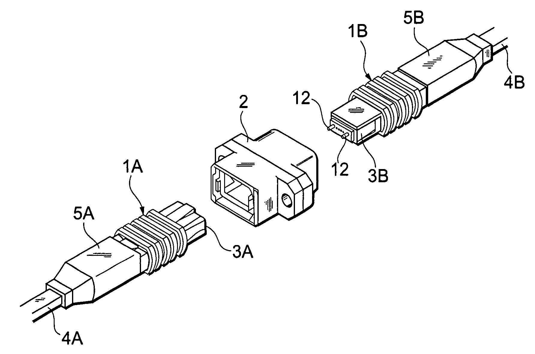
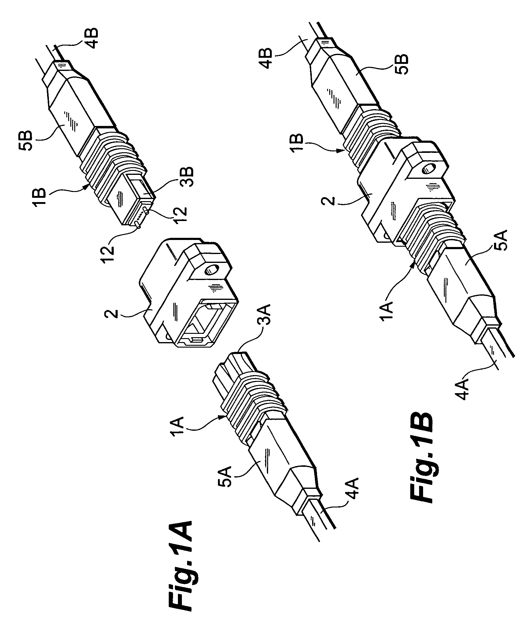
[0032]FIGS. 1A and 1B are perspective views showing the appearance of the optical connectors according to the first embodiment of the present invention. FIG. 1A is a view showing a state before connection between the optical connectors and FIG. 1B a view showing a state of connection between the optical connectors.

[0033]In these figures, the optical connectors 1A, 1B are MPO connectors, in which the optical connector 1A is constructed as a connector without guide pins and the optical connector 1B as a connector with guide pins 12. These optical connectors 1A, 1B are detachably connected through an adapter 2.

[0034]The optical connector 1A has a fer...


PUM


Abstract

An optical connector according to the present invention has a ferrule body provided with a fiber positioning hole, a pair of guide holes into which guide pins are inserted, and a connecting end face in which ends of the fiber positioning hole and guide holes open. A chamfer portion equivalent to a part of a surface of a body of revolution is formed at each guide hole on the connecting end face side. Further, the connecting end face is formed at an angle relative to a plane normal to the center axes of the pair of guide holes. In this structure, the slope of the connecting end face can suppress degradation of connection loss, and the provision of the chamfer portions can facilitate insertion of the guide pins, prevent damage of the connecting end face due to the guide pins, and also suppress degradation of connection loss due to the damage.

Description

CROSS-REFERENCE TO RELATED APPLICATIONS[0001]This is a Continuation-In-Part application of Ser. No. 10 / 055,012 filed on Jan. 25, 2002, now abandoned. And this is a Continuation-In-Part application of Ser. No. 10 / 084,664 filed on Feb. 28, 2002, now U.S. Pat. No. 6,676,300 which claims priority to Provisional Application No. 60 / 283,355, filed Apr. 13, 2001.BACKGROUND OF THE INVENTION[0002]1. Field of the Invention[0003]The present invention relates to a optical connector which positions and secures an end face of an optical fiber, and backplane assembly using this optical connector.[0004]2. Related Background Art[0005]One of methods of connecting ends of optical fibers to each other is a method of providing a connector structure at the ends of optical fibers. For constructing the connector structure at the ends of optical fibers, components called ferrules are used as members for positioning and securing the ends of optical fibers, facilitating the positioning of the ends to each othe...

Claims


Application Information

Patent Timeline
Patent Type & Authority Patents(United States)
IPC IPC(8): G02B6/38
CPCG02B6/3834G02B6/3847G02B6/3882G02B6/3885G02B6/3822G02B6/3854G02B6/3861G02B6/3863
Inventor OHTSUKA, KENICHIROKATSURA, HIROSHIUEDA, TOMOHIKOKAKII, TOSHIAKI
Owner SUMITOMO ELECTRIC IND LTD
Why Eureka
Try Eureka