Chain conveyor in the form of scales

a conveyor and scale technology, applied in the field of chain conveyors, can solve the problems of high wear and tear of conveyor belts made of rubber materials, significant deviations in dosing precision, and low precision of dosing, so as to reduce wear and tear.

Inactive Publication Date: 2005-11-15
PFISTER
View PDF36 Cites 18 Cited by
  • Summary
  • Abstract
  • Description
  • Claims
  • Application Information

AI Technical Summary

Benefits of technology

[0010]The same applies for the movable mounting of the driving elements which are held in an uncoupled manner via further intermediate joints. By interposing such intermediate joints, especially simple hinges or chain links which are arranged in an upright fashion, a kind of “card

Problems solved by technology

The disadvantageous aspect in the conventional arrangement of the chain conveyor is that the dosing precision can be relatively low when the conveyed material sticks to the driving element webs during the emptying or when disturbing forces from the conveyor chains alter the measurement.
This can lead to significant deviations concerning the dosing precision, which is important however for mixtures of addit

Method used


Image

  • Chain conveyor in the form of scales
  • Chain conveyor in the form of scales
  • Chain conveyor in the form of scales

Examples


Embodiment Construction

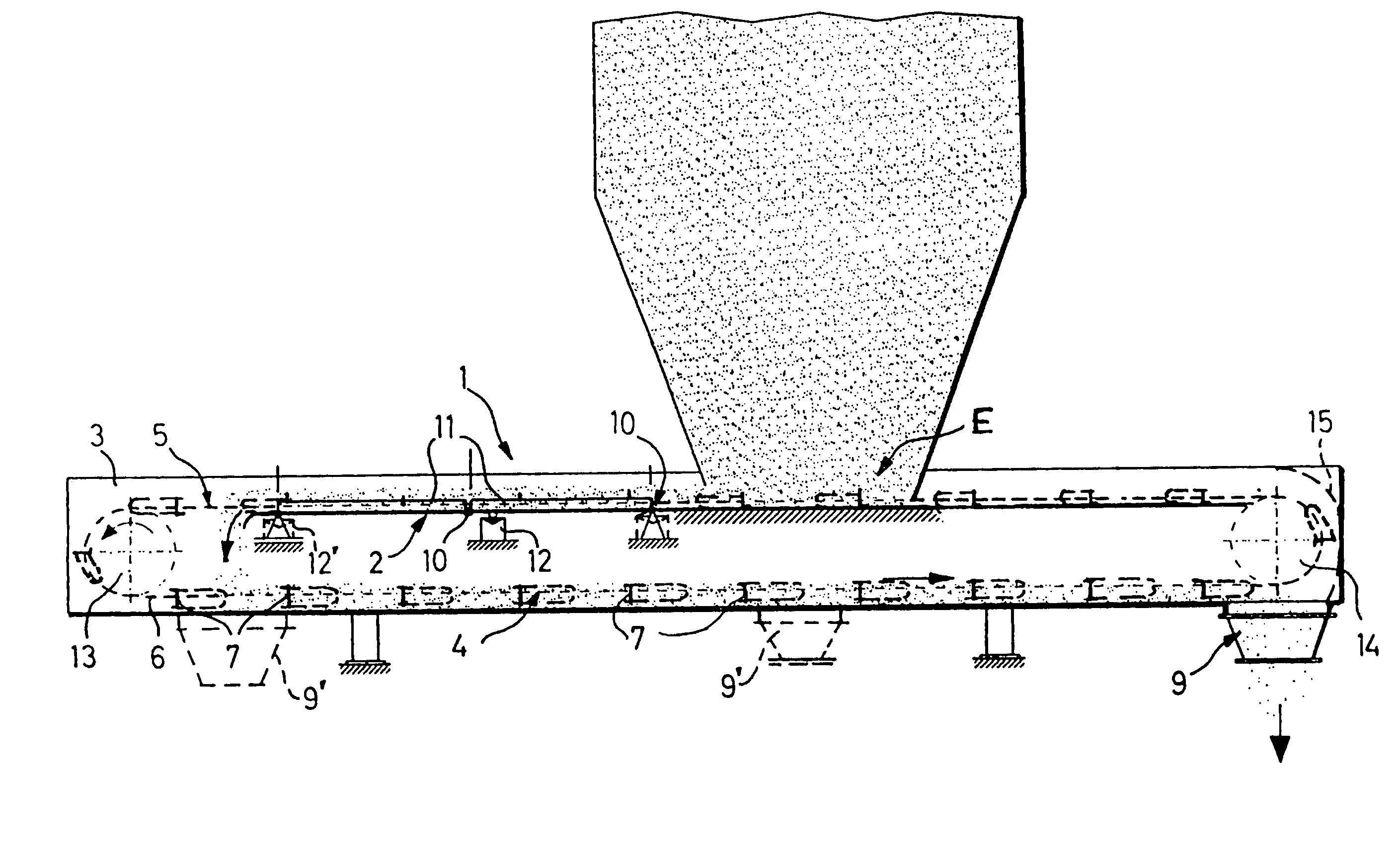
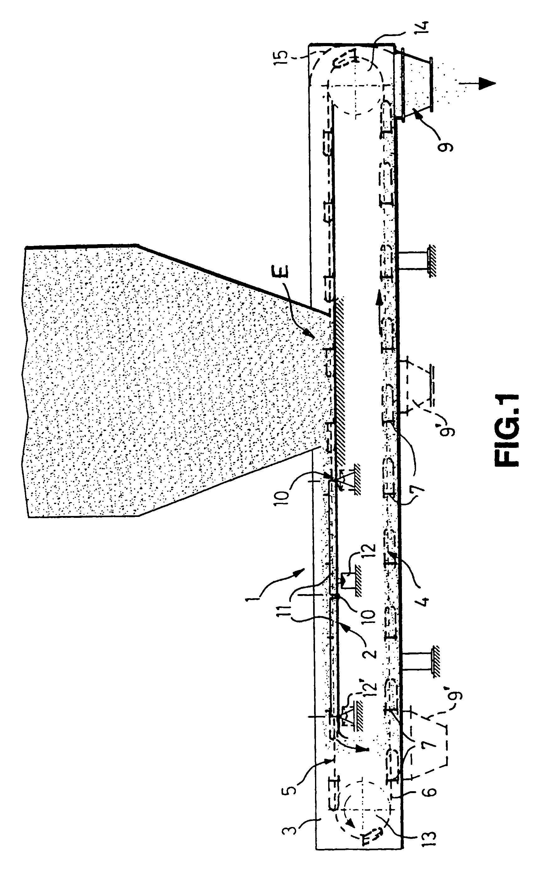
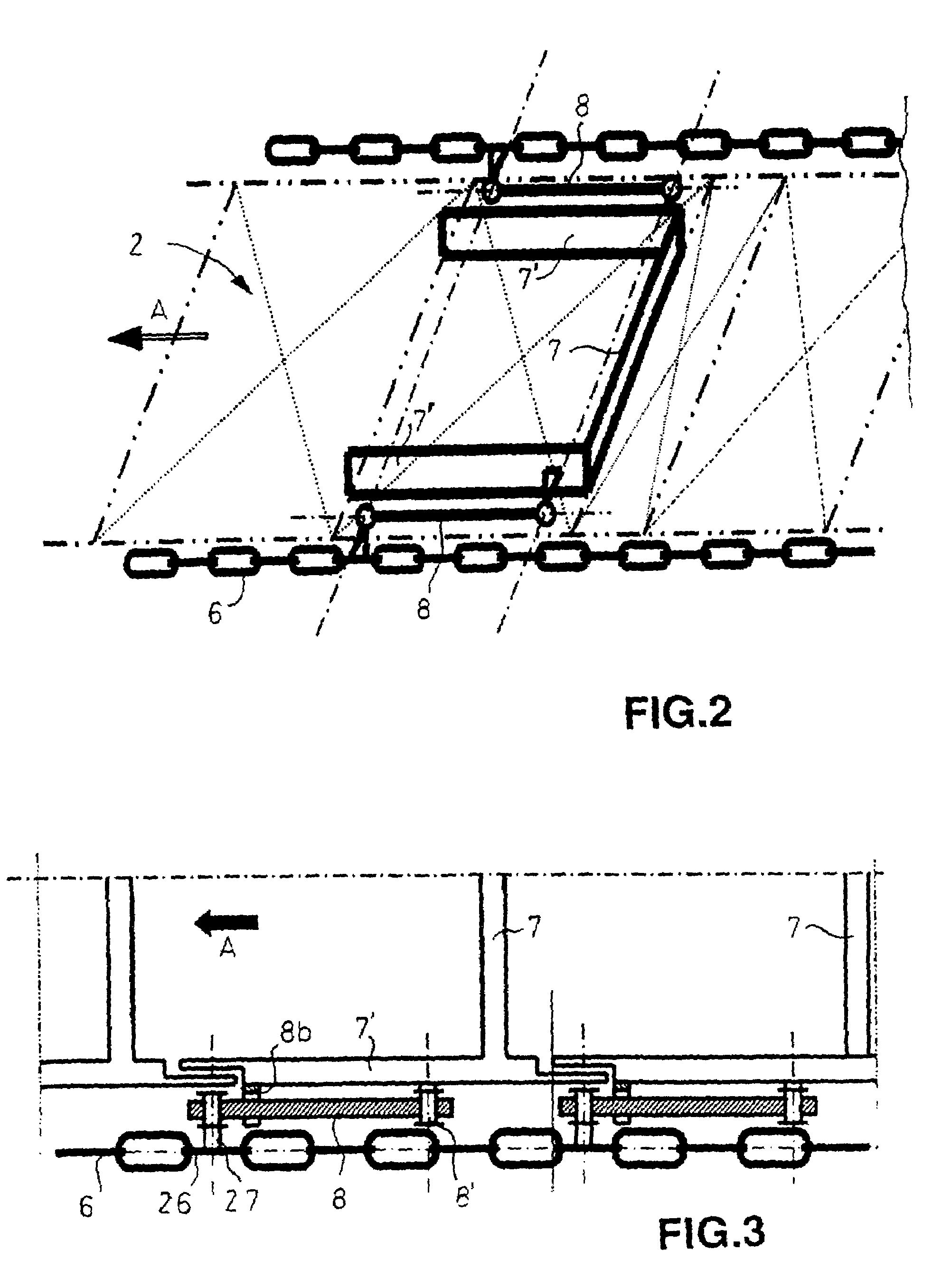
[0019]FIGS. 1 and 2 show a side view and a perspective view of a chain conveyor 1 in a housing or trough 3 which comprises a straight measuring section or measuring bridge 2 which is arranged on the upper run 5 of the belt. Conveyor chains 6 run along the measuring bridge 2 in a housing / trough 3, which conveyor chains comprise U-shaped conveying tools (in the top view) or driving elements 7. As a result of these drag-link driving elements 7, the bulk material which enters the housing 3 through an opening E (which in this case is a bunker or silo) is conveyed along the measuring bridge 2 in the carrying run 5 of the belt and then along the lower run 4 in a clockwise manner to an outlet opening 9, as is indicated here with the arrows. Between the inlet / filling opening E and the outlet opening 9 the plate-like measuring bridge 2 is held in a movable or slightly resilient fashion by means of flexible intermediate elements and is supported in this respect on a force measuring apparatus 1...


PUM


Abstract

A chain conveyor for gravimetrically measuring/dosing materials, especially bulk materials. The conveyor includes a housing/trough in which at least two chain conveyors with strip-shaped driving elements attached thereto rotate, wherein a measuring bridge that is supported on at least one force measuring device is arranged between the inlet and an outlet hole. The driving elements are mounted with multiple articulations on the conveyor chains, more particularly, said driving elements are inserted with positive-fit by lateral hinge bolts in the chain links located on the upper edge and configured to be placed flatly in the measuring bridge.

Description

RELATED APPLICATIONS[0001]This application is the U.S. National Phase of PCT / EP02 / 07018 filed Jun. 25, 2002 and claims priority to German Patent Application No. 101 30 022.0 filed Jun. 25, 2001, which are hereby incorporated herein by reference in their entirety.BACKGROUND OF THE INVENTION[0002]1. Field of the Invention[0003]The invention relates to a chain conveyor for gravimetrically measuring / dosing materials, especially bulk materials, with said conveyor comprising a housing / trough in which at least two conveyor chains with strip-shaped driving elements attached thereto rotate, as well as an inlet / filling opening and an outlet opening in the housing / trough, with at least one measuring bridge (2) which is supported on at least one force measuring apparatus is arranged between the inlet / filling and outlet opening.[0004]2. Description of the Related Art[0005]Such chain conveyors are used especially for conveying and weighing bulk materials. Such chain conveyors are also used increa...

Claims


Application Information

Patent Timeline
IPC IPC(8): B65G19/26B65G19/00B65G17/16G01G11/00G01G11/04B65G19/10B65G19/22
CPCB65G17/16B65G19/26G01G11/04B65G2201/04Y10S198/959G01G11/00
Inventor HAFNER, HANS WILHELM
Owner PFISTER
Why Eureka
Try Eureka