Diesel particulate filter monitoring using acoustic sensing

a technology of acoustic sensing and particulate filter, which is applied in the direction of fluid tightness measurement, combination devices, dispersed particle filtration, etc., can solve the problems of significant blow-by and filtering capability loss, and may not be able to achieve regeneration

Inactive Publication Date: 2005-11-15
AVL NORTH AMERICA
View PDF9 Cites 58 Cited by
  • Summary
  • Abstract
  • Description
  • Claims
  • Application Information

AI Technical Summary

Benefits of technology

[0005]The present invention provides a particulate filter system including an exhaust system transporting emissions from an engine. A filter such as a diesel particulate filter is disposed in the exhaust system. An acoustic sensor is associated with the exhaust system for detecting a preselected frequency, frequencies or ranges of the acoustic spectrum (including infra and ultrasound) passing through the filter. The selected frequency, frequencies or frequency ranges correspond to a filter state indicative of a clean, full, loading, or failed filter. One or more acoustic sensors may be fluidly or mechanically coupled to portions of the exhaust system to determine the effect on the measured frequencies

Problems solved by technology

There is also a need to determine if the filter is incapable of performing adequately such that regeneration may not be successfully performed due to a failure (breakdown, burn-through, etc.) of the substrate.
Al

Method used


Image

  • Diesel particulate filter monitoring using acoustic sensing
  • Diesel particulate filter monitoring using acoustic sensing
  • Diesel particulate filter monitoring using acoustic sensing

Examples


Embodiment Construction

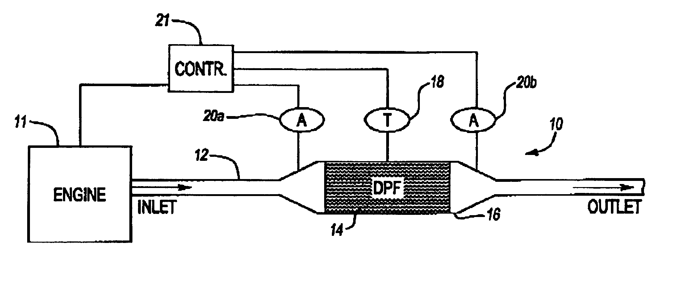
[0015]The present invention provides a method and apparatus to monitor the DPF soot loading and substrate failure. Several sensors may be used to monitor the DPF. A combination of pressure, temperature, and acoustical sensors may be used both upstream and downstream of the DPF to monitor its physical state. Additional information from the engine / exhaust controller may be used to quantify the exhaust flowing through the DPF.

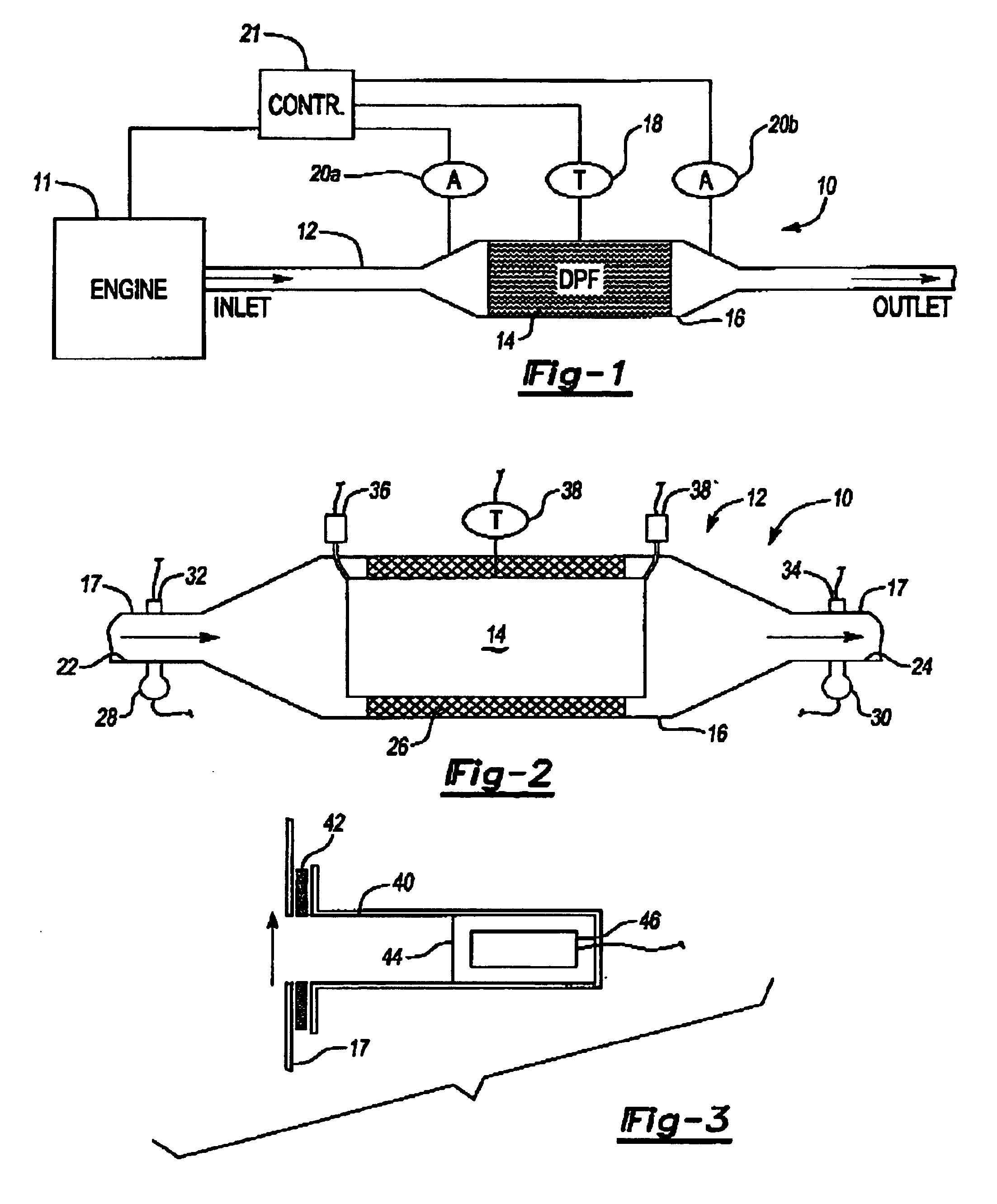
[0016]The present invention acoustic filter sensing system is shown at 10 in FIG. 1. System 10 is part of a powertrain system including an engine 11 connected to a portion of an exhaust system 12 having a particulate filter 14 disposed within a portion of the exhaust system 12. The filter 14 is typically constructed from a ceramic honeycomb-shaped material, as is known in the art. In prior art systems, pressure sensors are arranged on either side of the filter 14 to determine the pressure drop across the filter 14, as known in the art. Pressure sensors typically r...


PUM

PropertyMeasurementUnit
Frequencyaaaaaaaaaa
Frequencyaaaaaaaaaa
Frequencyaaaaaaaaaa

Abstract

A particulate filter system is provided including an exhaust system transporting emissions from an engine. A filter such as a diesel particulate filter is disposed in the exhaust system. An acoustic sensor is associated with the exhaust system for detecting one or more frequencies passing through the filter. The frequency corresponds to a filter state indicative of a clean, full, loading, or failed filter. One or more acoustic sensors may fluidly or mechanically coupled to portions of the exhaust system to determine the frequency caused by the exhaust flow through the filter. The acoustic emissions from the filter may be used to compare to a known filter state to determine the present filter state. Alternatively, more sophisticated mathematical approaches may be used in which processed filter information is compared to a known filter state to determine the present filter state.

Description

[0001]This application claims priority to Provisional Application Ser. No. 60 / 376,380, filed Apr. 29, 2002.BACKGROUND OF THE INVENTION[0002]This invention relates to a method and apparatus of monitoring the soot level in a diesel particulate filter.[0003]Diesel engines employed in commercial vehicles typically have filters arranged in the exhaust system to filter particulate matter from the exhaust to comply with emissions standards. The filter may be used numerous times after it has become saturated before a new filter must be installed. There is a need to measure the level of soot loading in diesel particulate filters (DPF) for determining when it is time to perform a filter regeneration cycle in which soot is removed from the filter when it has become too clogged. There is also a need to determine if the filter is incapable of performing adequately such that regeneration may not be successfully performed due to a failure (breakdown, burn-through, etc.) of the substrate.[0004]Pres...

Claims


Application Information

Patent Timeline
IPC IPC(8): B01D46/44B01D46/46F01N9/00F01N11/00B01D46/00G01N29/14G01N29/32G01N29/42
CPCB01D46/0086B01D46/446B01D46/448F01N9/002F01N9/005F01N11/00F01N11/002G01N29/14G01N29/326G01N29/42B01D2273/24B01D2279/30F01N2330/06F01N2550/04F01N2550/05F01N2550/12F02D2200/025F02D2200/0812G01N2291/0217Y02T10/47Y10S55/30Y02T10/40
Inventor RAUCHFUSS, MARK S.COOPER, STEPHEN R. W.ZAYAN, NICHOLAS M.
Owner AVL NORTH AMERICA
Why Eureka
Try Eureka