
Coated catalytic material with a metal phase in contact with a grain boundary oxide

a metal phase and grain boundary oxide technology, applied in the field of catalysts, can solve the problem that alkaline fuel cells have not found wide commercial acceptan

Inactive Publication Date: 2005-11-15
CHEVRONTEXACO TECH VENTURES
View PDF2 Cites 12 Cited by
  • Summary
  • Abstract
  • Description
  • Claims
  • Application Information

AI Technical Summary

Benefits of technology

"The present invention provides an industrial catalyst with metal particles distributed throughout the support and an enriched, catalytic metal surface. The metal particles can include non-noble metals, and the enriched metal surface can also include non-noble metals. The support is typically a metal oxide, and the metal particles can be native or non-native to the oxide support. The invention also provides a method for making the catalyst by forming a support with metal particles and enriching the surface with catalytic metal. The technical effect of this invention is to provide a catalyst with improved activity and selectivity for chemical reactions."

Problems solved by technology

Despite the above advances provided in the past, alkaline fuel cells have not found wide commercial acceptance due to the competing use of fossil fuels and the internal combustion engine.

Method used


Image

  • Coated catalytic material with a metal phase in contact with a grain boundary oxide
  • Coated catalytic material with a metal phase in contact with a grain boundary oxide
  • Coated catalytic material with a metal phase in contact with a grain boundary oxide

Examples


example 1

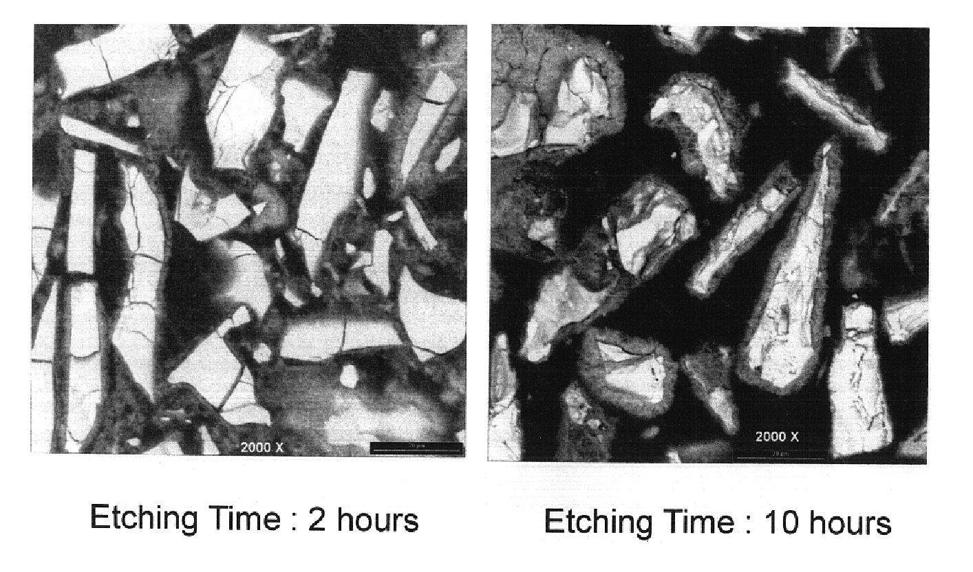
[0085]1. A starting alloy was prepared by melt / casting an alloy having a composition La—Ce—Pr—Nd—Ni—Co—Mn—Al having an A to B ratio of about 5.15 and forming a powder thereform. 500 g powder was etched in 60 wt % KOH for 1 hour at 110° C., filtered and rinsed with water. The powder was combined with 8wt % nickel provided from nickel chloride in 30% KOH at 110° C. for 2 hours with constant stirring, filtered, rinsed with water. The prepared material was then formed into an anode.

[0086]2. For comparison purposes, the starting alloy from 1. above was etched in 60 wt % KOH for 10 hours at 110° C., filtered and rinsed with water. The material was formed into an anode.

[0087]3. For comparison purposes, starting alloy from 1. above was etched in 60 wt % KOH for 2 hours at 110° C., filtered and rinsed with water. The material was formed into an anode.

[0088]4. For comparison purposed, an anode was prepared from commercial catalyst material.

[0089]The electrodes were tested in side-by-side comp...

example 2

[0090]Materials were prepared for magnetic susceptibility testing. Five samples were prepared using powder prepared from the initial alloy of Example 1. The first sample was virgin, unetched material. The second material was combined with 60% KOH for 1 hour at 110° C. The third material was combined for with 60% KOH for 2 hours at 110° C. The fourth material was combined with 60 wt % KOH for 1 hour at 110° C., filtered and rinsed with water and then further treated for 1 hour with 30 wt % KOH at 110° C. The fifth material having a metal at least partially covering the catalyst was prepared as described in 1. above. The results are listed in Table 1 below.

[0091]

TABLE 1Magnetic SusceptibilityMsTreatment1 / memu / g1. Virgin, unetched material84.32. 1 hr 60% KOH8973. 2 hr 60% KOH10904. 1 hr 60% KOH, 2 hrs 30% KOH11895. 1 hr 60% KOH, 2 hrs 30% KOH w / high surface area nickel1216

Magnetic susceptibility is a surface measurement that is used to indicate the presence of metal. As shown in Table ...


PUM

PropertyMeasurementUnit
sizeaaaaaaaaaa
diameteraaaaaaaaaa
diameteraaaaaaaaaa

Abstract

An industrial catalyst having: a support; a plurality of metallic particulates distributed throughout the support; and a metal at least partially covering the surface of the support.A method for making a catalyst including the steps of: forming a support with non-noble metal particulates distributed throughout the support; and at least partially covering the surface of the support with a metal.

Description

REFERENCE TO RELATED APPLICATIONS[0001]The present invention is a continuation in part of U.S. patent application Ser. No. 09 / 859,164, now U.S. Pat. No. 6,740,448, entitled “Modified Electrochemical Hydrogen Storage Alloy Having Increased Capacity, Rate Capability and Catalytic Activity”, filed May 16, 2001 which is a divisional application from U.S. patent application Ser. No. 09 / 575,313, now U.S. Pat. No. 6,461,766, filed May 19, 2000 and U.S. patent application Ser. No. 09 / 290,633, now U.S. Pat. No. 6,270,719, filed Apr. 12, 1999; and is a continuation in part of U.S. patent application Ser. No. 09 / 523,820, now U.S. Pat. No. 6,841,512, entitled “Finely Divided Metal Catalyst And Method For Making The Same”, filed Mar. 13, 2000, the disclosures of which are herein incorporated by reference.BACKGROUND OF THE INVENTION[0002]I. Field of the Invention[0003]The present invention pertains generally to catalysts and more specifically to electrocatalysts, hydrogenation catalysts, hydrocra...

Claims


Application Information

Patent Timeline
Patent Type & Authority Patents(United States)
IPC IPC(8): B01J23/00H01M4/52H01M4/38B01J21/08B01J29/04H01M4/90H01M4/86H01M4/88H01M8/12H01M10/34
CPCH01M4/885H01M4/90H01M4/9066H01M4/9075H01M4/8657Y02E60/50B01J37/02B01J23/89B01J23/755B01J23/38
Inventor OVSHINSKY, STANFORD R.REICHMAN, BENJAMINFETCENKO, MICHAEL A.YOUNG, KWOMAYS, WILLIAMSTREBE, JAMES
Owner CHEVRONTEXACO TECH VENTURES
Learn More