MRI system utilizing supplemental static field-shaping coils

a static field and coil technology, applied in superconducting magnets/coils, instruments, magnetic bodies, etc., can solve the problems of inability to achieve the desired gradient field quality in space and time, field strength limitation, cost and impracticality of shielding, etc., to achieve the effect of minimizing design requirements and associated costs, reducing the generation of undesired eddy current heating, and increasing the static magnetic field strength and uniformity

Active Publication Date: 2005-11-15
GE MEDICAL SYST GLOBAL TECH CO LLC
View PDF6 Cites 19 Cited by
  • Summary
  • Abstract
  • Description
  • Claims
  • Application Information

AI Technical Summary

Benefits of technology

[0011]The embodiments of the present invention provide several advantages. One advantage provided by an embodiment of the present invention is the provision of a MRI system that incorporates the use of supplemental static field-shaping coils. The field-shaping coils increase strength and uniformity of the static magnetic field while minimizing generation of undesired eddy current heating from the pulsed gradient coils. The field-shaping coils may be unshielded from the pulsed gradient coils, which minimizes design requirements and associated costs thereof.
[0012]Another advantage provided by an embodiment of the present invention is the provision of a supplemental static field-shaping coil housing, which further minimizes induction of eddy currents within the MRI system.
[0013]Furthermore, the present invention provides multiple superconducting magnet styles, magnet arrangements, and cooling configurations, which increase versatility in design of both cylindrical and open architecture configured MRI systems, as well as other configured MRI systems.

Problems solved by technology

These eddy currents in turn produce their own magnetic fields, which degrade the quality of the desired gradient field in space and time.
Thus, a field strength limitation arises when maintaining the stray MR field below a specified level to minimize or prevent individuals outside of the MRI room from being effected by the field.
In order to minimize the field, the MRI room may be shielded from the surrounding environment, however the shielding can be costly and impractical.
Thus, prior MRI system designs do not satisfy the minimal acceptable gap requirement, the minimal stray field requirement, and provide the desired static magnetic field uniformity.
Similar infeasibilities exist for cylindrical MRI system designs, especially ones of a “Short”or more compact design.

Method used


Image

  • MRI system utilizing supplemental static field-shaping coils
  • MRI system utilizing supplemental static field-shaping coils
  • MRI system utilizing supplemental static field-shaping coils

Examples


Embodiment Construction

[0022]In each of the following figures, the same reference numerals are used to refer to the same components. While the present invention is described with respect to a system for generating a highly uniform static magnetic field, the present invention may be applied to various systems including: magnetic resonance imaging (MRI) systems, MR spectroscopy systems, and other applications. The present invention may be applied to both cylindrical and open architecture style MRI systems.

[0023]In the following description, various operating parameters and components are described for one constructed embodiment. These specific parameters and components are included as examples and are not meant to be limiting.

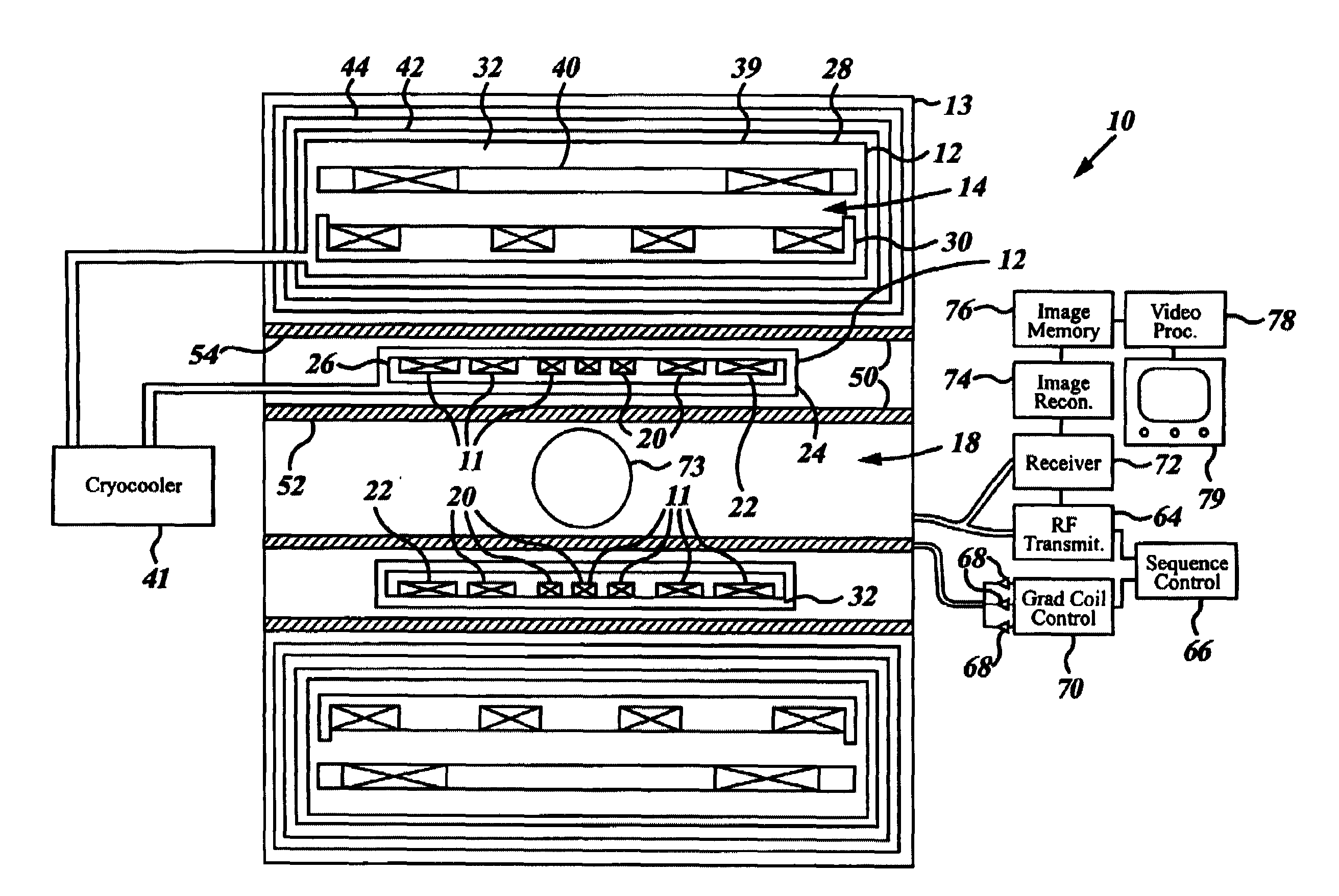
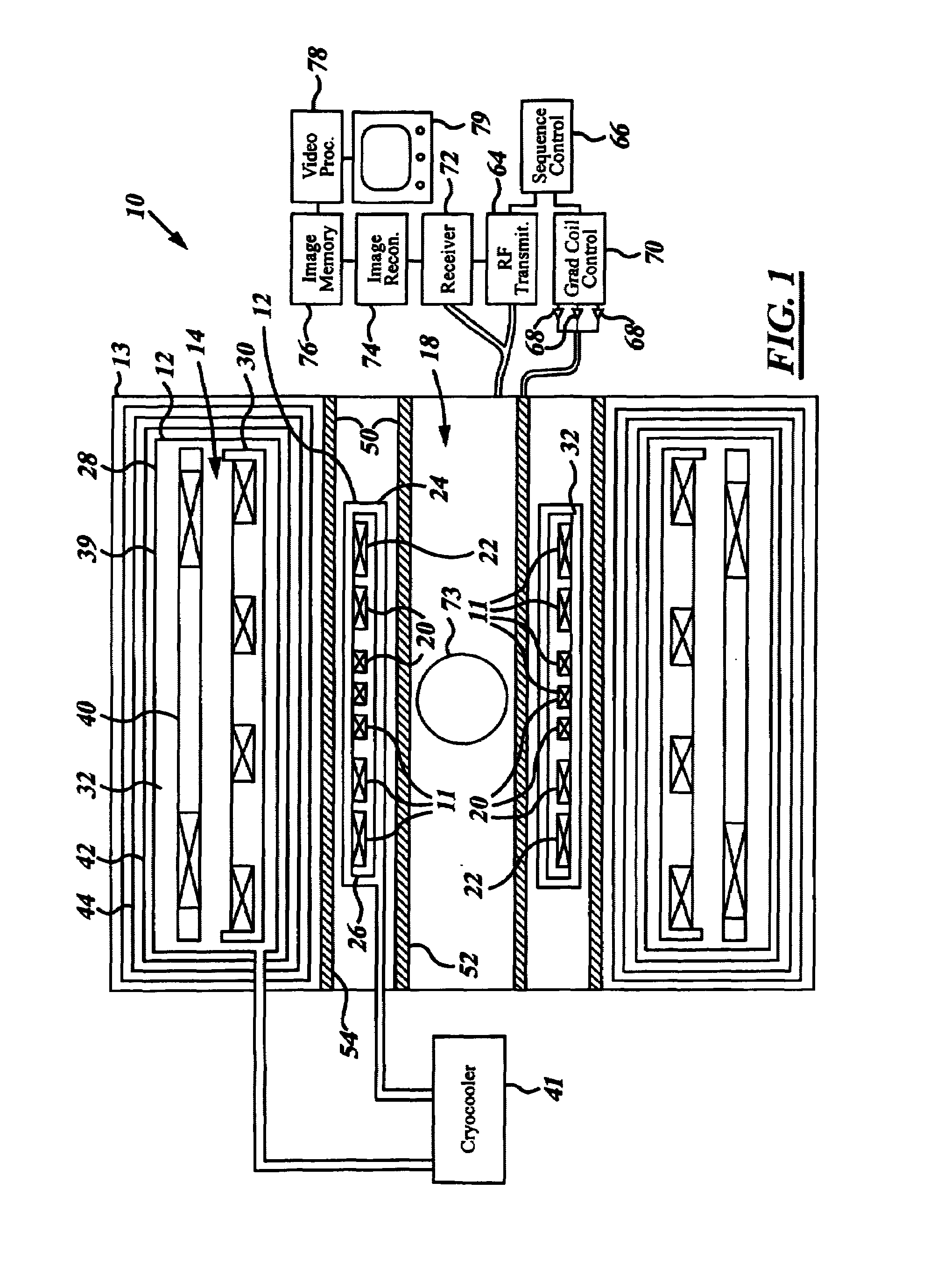
[0024]Referring now to FIG. 1, a block diagammatic view of a MRI system 10 incorporating use of supplemental static field-shaping coils 11 and using coolant vessels 12 for cooling in accordance with an embodiment of the present invention is shown. The MRI system 10 includes a static ma...


PUM

PropertyMeasurementUnit
magnetic resonance imagingaaaaaaaaaa
static magnetic fieldaaaaaaaaaa
superconductingaaaaaaaaaa

Abstract

A magnetic resonance imaging system (10) includes a superconducting magnet (14) that generates a static magnetic field. A gradient coil assembly (50) with an associated patient bore enclosure (18) and a gradient coil (52) that generates a gradient magnetic field in the patient bore (18). A static field-shaping coil (11) resides between the superconducting magnet (14) and the patient bore (18) and supplements the static magnetic field.

Description

BACKGROUND OF INVENTION[0001]The present invention relates generally to Magnetic Resonance Imaging (MRI) systems, and more particularly, to a system for generating a highly uniform static magnetic field.[0002]Magnetic Resonance Imaging (MRI) systems are generally in either a cylindrical or an open architecture configuration. Both the cylindrical and open architecture configurations include a superconducting magnet that generates a temporally constant primary magnetic field. The superconducting magnet resides within a cryostat, which cools the superconducting magnet and maintains the operating temperature thereof. The temperature of the superconductor is maintained at approximately 4–10° K., for low temperature superconductors, and at approximately 20–80° K. for high temperature superconductors. The cryostat is typically contained within several thermal shields.[0003]The superconducting magnet is used in conjunction with a first set of magnetic gradient coils, which are sequentially ...

Claims


Application Information

Patent Timeline
Patent Type & Authority Patents(United States)
IPC IPC(8): G01R33/3875G01R33/38G01R33/3815A61B5/055G01R33/385H01F6/00
CPCG01R33/3815G01R33/3875
Inventor HAVENS, TIMOTHY J.
Owner GE MEDICAL SYST GLOBAL TECH CO LLC
Why Eureka
Try Eureka