
Image displaying with multi-gradation processing

a multi-gradation processing and display device technology, applied in the field of image display apparatuses, can solve problems such as discontinuous gradation levels, multi-gradation processing with error diffusion, and loss of gradation

Inactive Publication Date: 2005-11-15
RAKUTEN GRP INC
View PDF27 Cites 38 Cited by
  • Summary
  • Abstract
  • Description
  • Claims
  • Application Information

AI Technical Summary

Benefits of technology

The present invention provides an apparatus and method for displaying images with no color distortion or pattern noises. The apparatus includes a detector to detect the gradation level of the input video signal and a processor to depress the color saturation level of the video signal in a predetermined gradation level range. The apparatus can also convert the input video signal to a different gradation level range based on the detected gradation level range. The invention also provides a reverse-gamma correction method to switch between a state where the input video signal requires conversion and a state where the input video signal does not require conversion. The technical effects of the invention include improved image quality and reduced color distortion.

Problems solved by technology

Such a decrease however loses gradation; hence multi-gradation processing with error diffusion is required.
Displaying images with reverse-gamma correction to digitally-converted R-, G- and B-video signals, as disclosed above, loses gradation particularly in the low intensity range, thus resulting in discontinuous gradation levels.
This results in color pseudo-contour disturbances in image quality or in images with color saturation in which some dot bits have been dropped, particularly, for dark images at flat color saturation levels.
This processing, however, causes disturbances in image quality, like periodical color pattern noises on black dark images.
This method, however, uniformly decreases color saturation in the low intensity range even for images of a large saturation in the low intensity range, thus producing strange images.
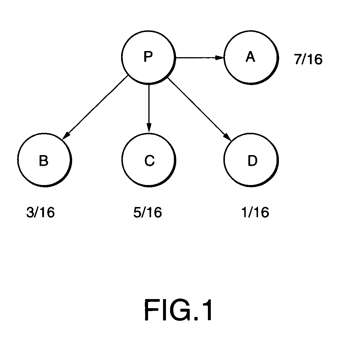
Error diffusion as illustrated in FIG. 1 uses the same error diffusion coefficients to the three primary colors R, G and B, thus causes image disturbances, such as, periodical pattern noises peculiar to error diffusion, especially, for displaying fixed patterns.
Displaying images without error diffusion thus remarkably loses gradation levels in the low gradation range, thus producing images with remarkably discontinuous gradation levels in which digital bits have been dropped.

Method used


Image

  • Image displaying with multi-gradation processing
  • Image displaying with multi-gradation processing
  • Image displaying with multi-gradation processing

Examples


first embodiment

[0119]As disclosed above, the video signal processing achieves preferable color reproduction with no color quasi edge-like image disturbances in a specific gradation range such as the low gradation range, images of color saturation as if bits have been dropped or color pattern noises by detecting a gradation level of an input video signal to adaptively depress the color saturation level in a color saturation range having a predetermined color saturation level of the input video signal only in a gradation range having a predetermined gradation level.

The Second Preferred Embodiment

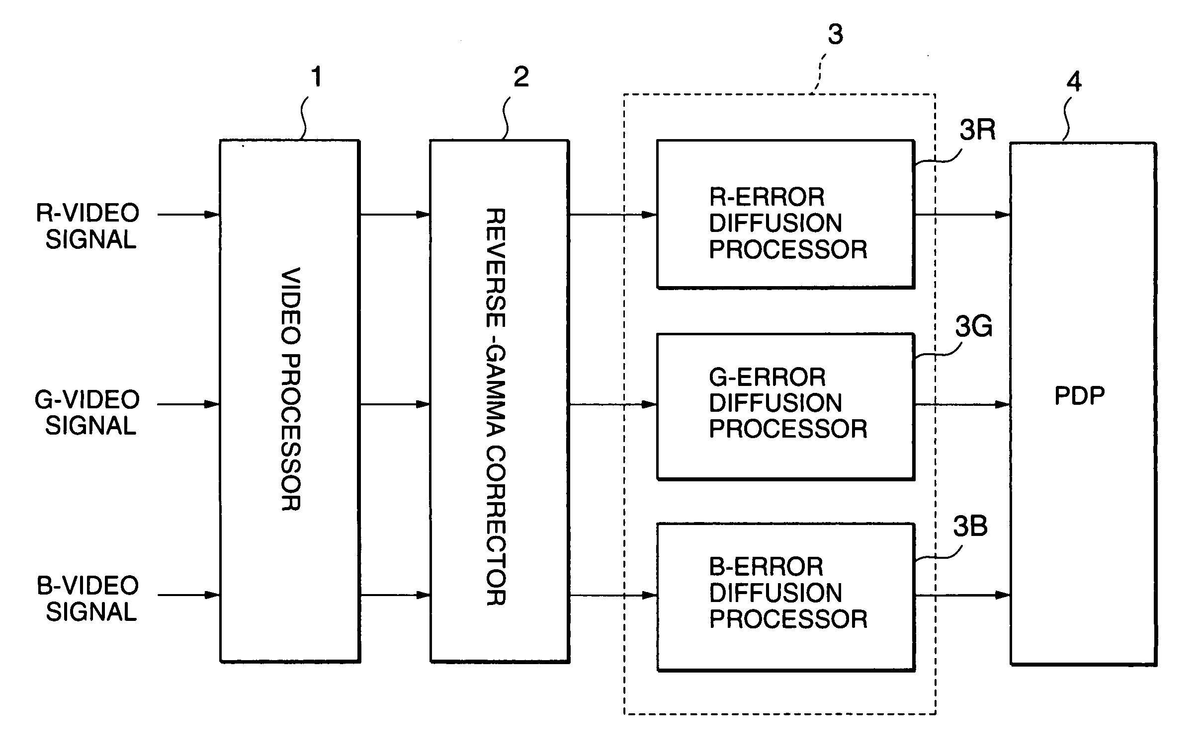
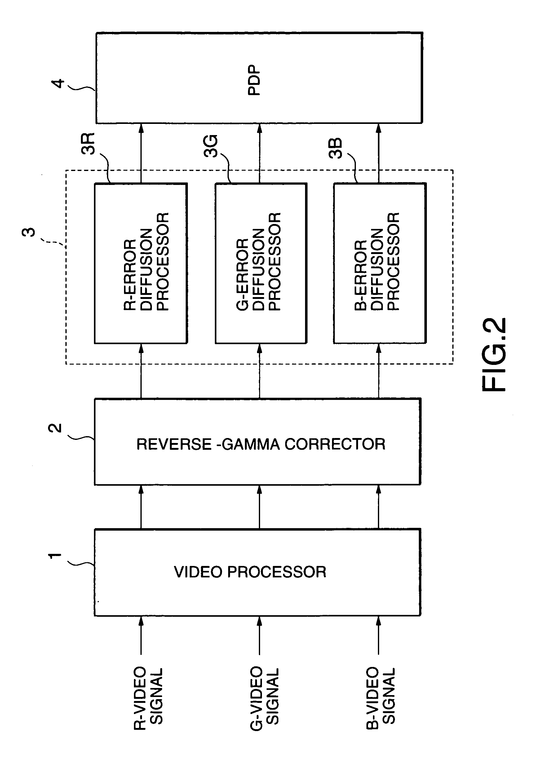
[0120]The second embodiment relates to error diffusion processing. The overall circuit configuration of a displaying apparatus used for the second embodiment is like shown in FIG. 2 for the first embodiment.

[0121]Elements in this embodiments and also those in the third to the fifth embodiments which will be described later, that are the same or analogous to the elements in the first embodiment are reference...

second embodiment

[0123]As shown in FIG. 13, an R-error diffusion processor 30R, a G-error diffusion processor 30G, and a B-error diffusion processor 30B for the second embodiment have the same circuitry, the block diagrams for the processors 30G and 30B being omitted for brevity.

[0124]Error diffusion coefficients set in these processors are different from each other. However, since the operation is the same, the following disclosure is only for the R-error diffusion processor 30R, for brevity.

[0125]In FIG. 13, a 12-bit R-signal fed by the reverse-gamma corrector 2 (FIG. 2) is output via adders 31 and 32. The lower 4 bits of the 12-bit data output by the adder 32 are fed to a R-error detector 33R. The lower 4 bits correspond to the gradation difference that will be lost by converting the 12-bit digital signal (4096 gradations) to the 8-bit digital signal (256 gradations).

[0126]The R-error detector 33R generates error data by multiplying the input lower 4-bit data by error diffusion coefficients, acco...

third embodiment

[0143]The feature of the third embodiment lies in that the number of bits used for error diffusion to either of input R-, G- and B-signals, or the number of bits to be diffused to the upper 8-bits for error diffusion to either of the input signals is different from the other or all of the bits for error diffusion to the three input signals are different from each other.

[0144]The circuit configuration for the third embodiment is the same as shown in FIG. 13 for the second embodiment; hence the operation of the third embodiment will be described with reference to FIG. 13.

[0145]In FIG. 13, a 12-bit R-signal fed by the reverse-gamma corrector 2 (FIG. 2) is output via the adders 31 and 32. The lower 4 bits of the 12-bit data output by the adder 32 are fed to the R-error detector 33R. The lower 4 bits correspond to gradation difference that will be lost by converting the 12-bit digital signal (4096 gradations) to an 8-bit digital signal (256 gradations).

[0146]The R-error detector 33R gene...


PUM


Abstract

A video signal processing apparatus processes an input video signal for displaying an image based on the video signal. Detected is a gradation level of the input video signal. A color saturation level of the input video signal is depressed in a predetermined color saturation level range only when the detected gradation level is located in a predetermined gradation level range. A first input video signal having a first gradation level (or number of bits) is converted into a second video signal having a second gradation level (or number of bits) that is lower (or smaller) than first gradation level (or number of bits), for displaying an image based on the input video signal. Error data is generated in response to a data portion of the first input video signal. The data portion corresponds to a difference between the first and the second gradation levels (or number of bits). The error data is obtained by multiplying the data portion by predetermined error diffusion coefficients according to pixel dots that surround a pixel dot composed of R(red)-, G(green)- and B(blue)-signal components of the first input video signal. At least one of the number of bits of the error diffusion coefficients for one of the R-, G- and B-signal components is different from the other number of bits of the error diffusion coefficients for the other signal components The generated error data is added to the first input video signal to convert the first input video signal into the second video signal. Reverse-gamma correction may be applied to the first input video signal before conversion.

Description

BACKGROUND OF THE INVENTION[0001]The present invention relates to an image displaying apparatus for displaying images with digitally limited intermediate gradation levels, such as, plasma display panels (PDP), field emission display (FED)s, digital micro mirror devices (DMD) and electroluminescence displays (EL), and video signal processor. This invention also relates to video signal processing and error diffusion (variance) processing used for such image displaying apparatus.[0002]Among image displaying apparatus, matrix-type image displaying apparatus, such as, a PDP for displaying images with gradation by dividing one field into sub-fields, a FED for displaying images with gradation by pulse-width modulation (PWM), and also a DMD, display images only at digitally-limited intermediate gradation levels.[0003]Television broadcast generally provides gamma correction at the transmission side for cathode-ray tubes (CRTs) as receivers to achieve the linear characteristics with the rever...

Claims


Application Information

Patent Timeline
Patent Type & Authority Patents(United States)
IPC IPC(8): G09G3/20G09G5/02H04N9/77
CPCG09G3/2003G09G3/2059H04N9/77G09G3/2077G09G3/2803G09G2320/0276
Inventor MASUJI, SHIGEHIROAIBA, HIDEKI
Owner RAKUTEN GRP INC
Learn More