
Optical processor

a technology of optical processors and processors, applied in the field of optical signal processing, can solve the problems of high cost, lack of flexibility, and inability to apply widely, and achieve the effect of preventing widespread application and reducing costs

Inactive Publication Date: 2005-11-15
OL SECURITY LIABILITY CO
View PDF32 Cites 48 Cited by
  • Summary
  • Abstract
  • Description
  • Claims
  • Application Information

AI Technical Summary

Benefits of technology

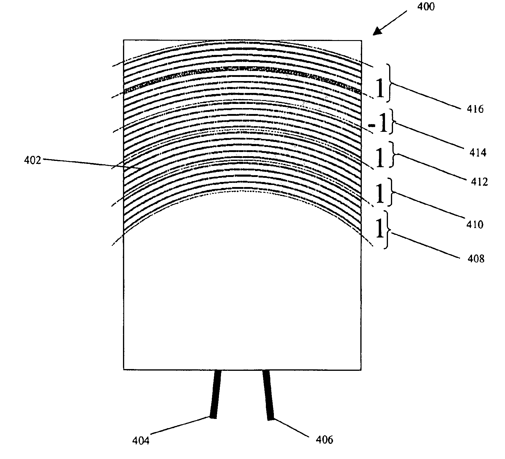
[0013]Method and apparatus are disclosed for optical packet decoding, waveform generation and wavelength multiplexing/demultiplexing using a programmed holographic structure. A configurable programmed ...

Problems solved by technology

In many cases these shortcomings, including limited spectral resolution, alignment sensitivity, fabrication difficulties, high cost, and lack of flexibility, have prevented widespread application.
Programmed diffractive structures known in the art do not provide for the implementation of general wavefront transformations simultaneously with general spectral transformations.
Programmed surface gratings and programmed fiber gratings are encumbered with severe functional constraints.
A programmed surface-grating filter has a fundamentally low efficiency when used to implement complex spectral transformations, and requires alignment sensitive free-space optical elements to function.
Furthermore, when light is input to the device and output from the device using only the single propagating mode of the fiber, programmed single-mode fiber-grating filters can only support a single transfer function within a given spectral window.

Method used


Image

  • Optical processor
  • Optical processor
  • Optical processor

Examples


Embodiment Construction

[0027]In the following description, various aspects of the present invention will be described. However, it will be apparent to those skilled in the art that the present invention may be practiced with only some or all aspects of the present invention. For purposes of explanation, specific numbers, materials and configurations are set forth in order to provide a thorough understanding of the present invention. However, it will also be apparent to one skilled in the art that the present invention may be practiced without the specific details. In other instances, well known features are omitted or simplified in order not to obscure the present invention.

[0028]Various operations will be described as multiple discrete steps in turn, in a manner that is most helpful in understanding the present invention. However, the order of description should not be construed as to imply that these operations are necessarily order dependent. In particular, these operations need not be performed in the...


PUM


Abstract

Method and apparatus are disclosed for optical packet decoding, waveform generation and wavelength multiplexing / demultiplexing using a programmed holographic structure. A configurable programmed holographic structure is disclosed. A configurable programmed holographic structure may be dynamically re-configured through the application of control mechanisms which alter operative holographic structures.

Description

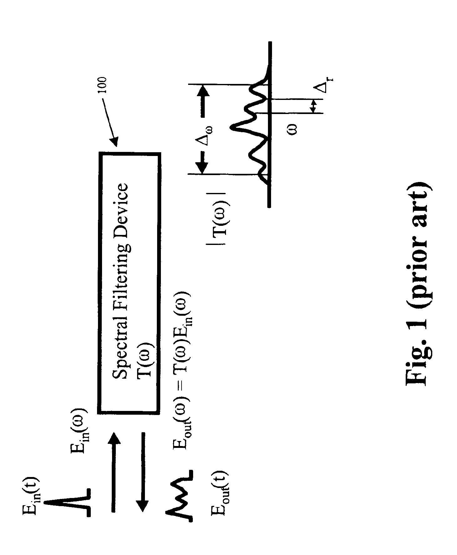
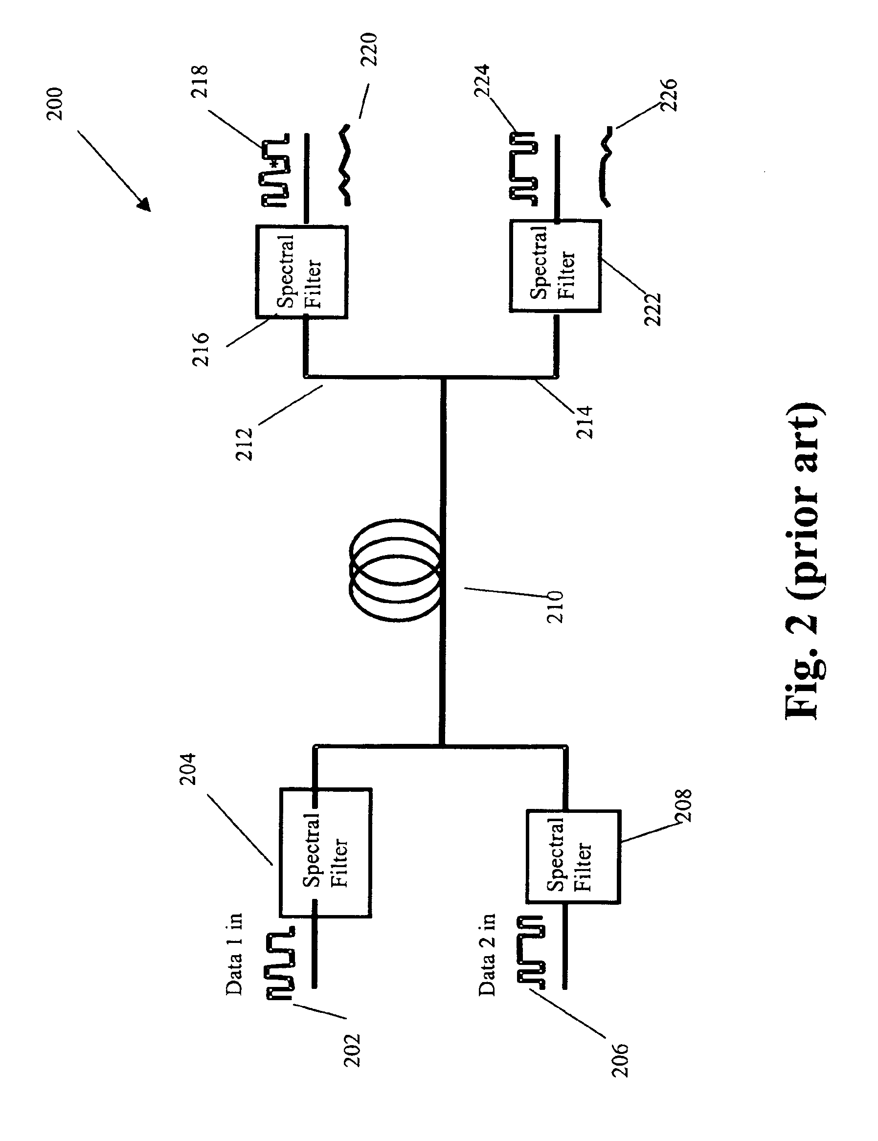
[0001]This U.S. patent application is a Continuation in Part from U.S. non-provisional application Ser. No. 09 / 811,081, titled “Holographic Spectral Filter,” filed Mar. 16, 2001, which claims the benefit of U.S. Provisional Application No. 60 / 190,126, filed Mar. 16, 2000, and of U.S. Provisional Application No. 60 / 199,790 filed Apr. 26, 2000, and of U.S. Provisional Application No. 60 / 235,330 filed Sep. 26, 2000, and of U.S. Provisional Application No. 60 / 247,231 filed Nov. 10, 2000.FIELD[0002]The field of interest is optical signal processing.BACKGROUND[0003]Spectral filtering is a very useful optical function that can be utilized to control the temporal waveform of pulsed optical signals, to cross-correlate or otherwise process optical signals, and to differentially control and manipulate spectrally-distinguished optical communication channels, as found for example in wavelength-division-multiplexed (WDM) optical communication systems. Devices have been introduced over the years t...

Claims


Application Information

Patent Timeline
IPC IPC(8): G02B6/124G02B5/20G02B6/34G02B5/32G03H1/04G02B6/12
CPCG02B5/203G02B5/32G02B6/12007G02B6/124G02B6/29322G02B6/29326G02B6/29328G02B6/29395G03H1/0248G02B2006/12164G03H1/0005G03H2225/23H04J14/02H04J14/0201
Inventor MOSSBERG, THOMAS W.
Owner OL SECURITY LIABILITY CO
Learn More