
Source synchronous link integrity validation

a source synchronous link and integrity validation technology, applied in the field of computer systems, can solve the problem that the noise of the first transition tends to decrease the rate of the first transition

Inactive Publication Date: 2005-11-15
ORACLE INT CORP
View PDF12 Cites 378 Cited by
  • Summary
  • Abstract
  • Description
  • Claims
  • Application Information

AI Technical Summary

Benefits of technology

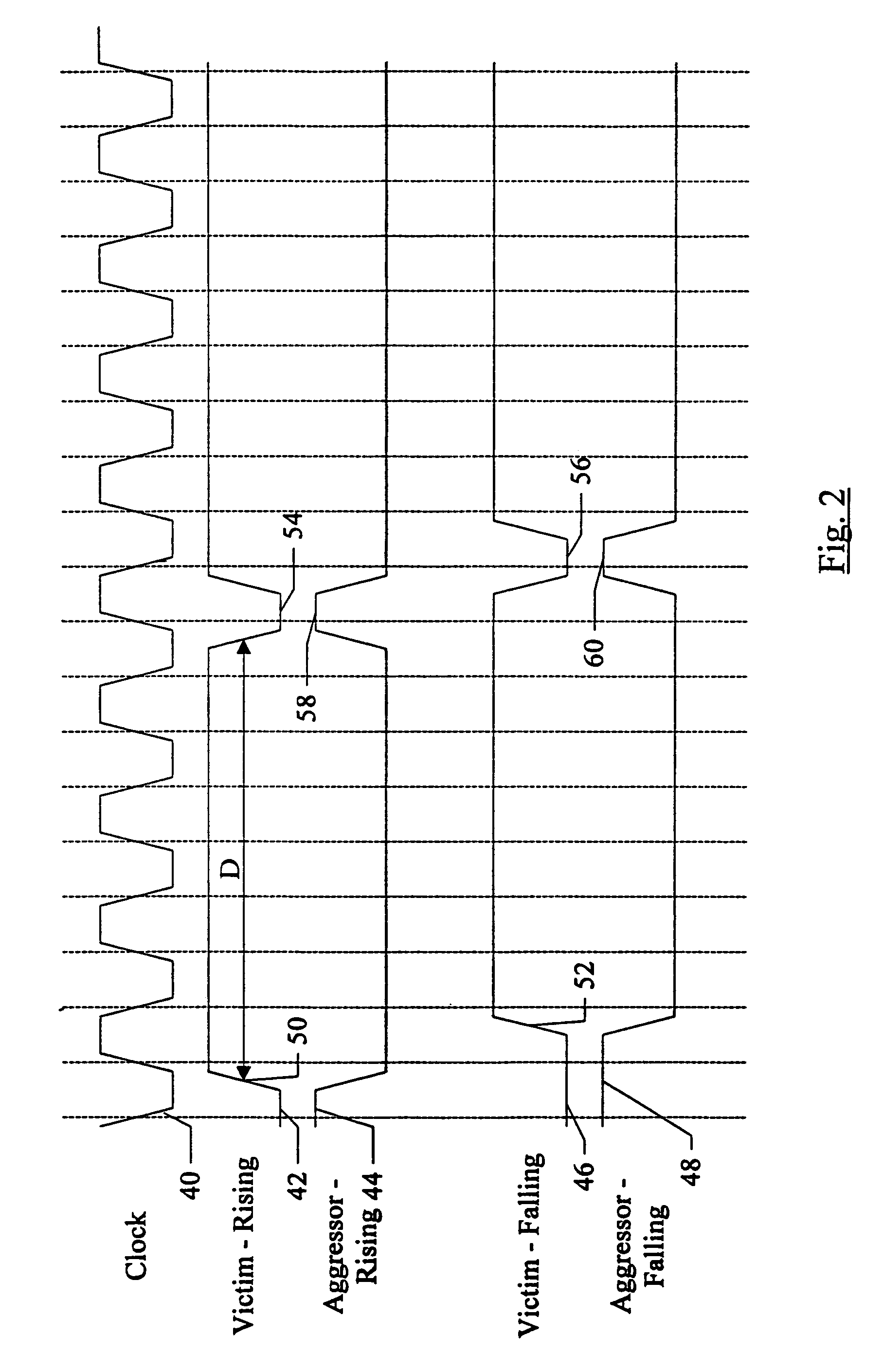
[0008]Additionally, in one embodiment, the system may perform repeated iterations of the transition weave pattern while varying the timing of the previous transition on the victim line (to create the reflection) with respect to the first crossing pulse on the victim line. Performing the test in this fashion may approximate the “worst case” interaction of the reflection with the crossing pulses. Furthermore, performing the test in this fashion may allow for a flexible implementation of test circuitry within the system since the test may cover links of varying lengths (and thus varying reflection timings). Accordingly, test circuitry need not be customized to the particular link to be tested. Additional iterations of the test may be performed to vary the timing of the previous transition on the victim line (to create the reflection) with respect to the first crossing pulse in combination with varying the polarity of the pulse, the clock edge to which the pulse is aligned, and the line under test (the “victim line”).

Problems solved by technology

In either case, the first transition of the first crossing pulse is concurrent with transitions of the same polarity on the aggressor lines, and thus SSO noise tends to decrease the rate of the first transition.

Method used


Image

  • Source synchronous link integrity validation
  • Source synchronous link integrity validation
  • Source synchronous link integrity validation

Examples


Embodiment Construction

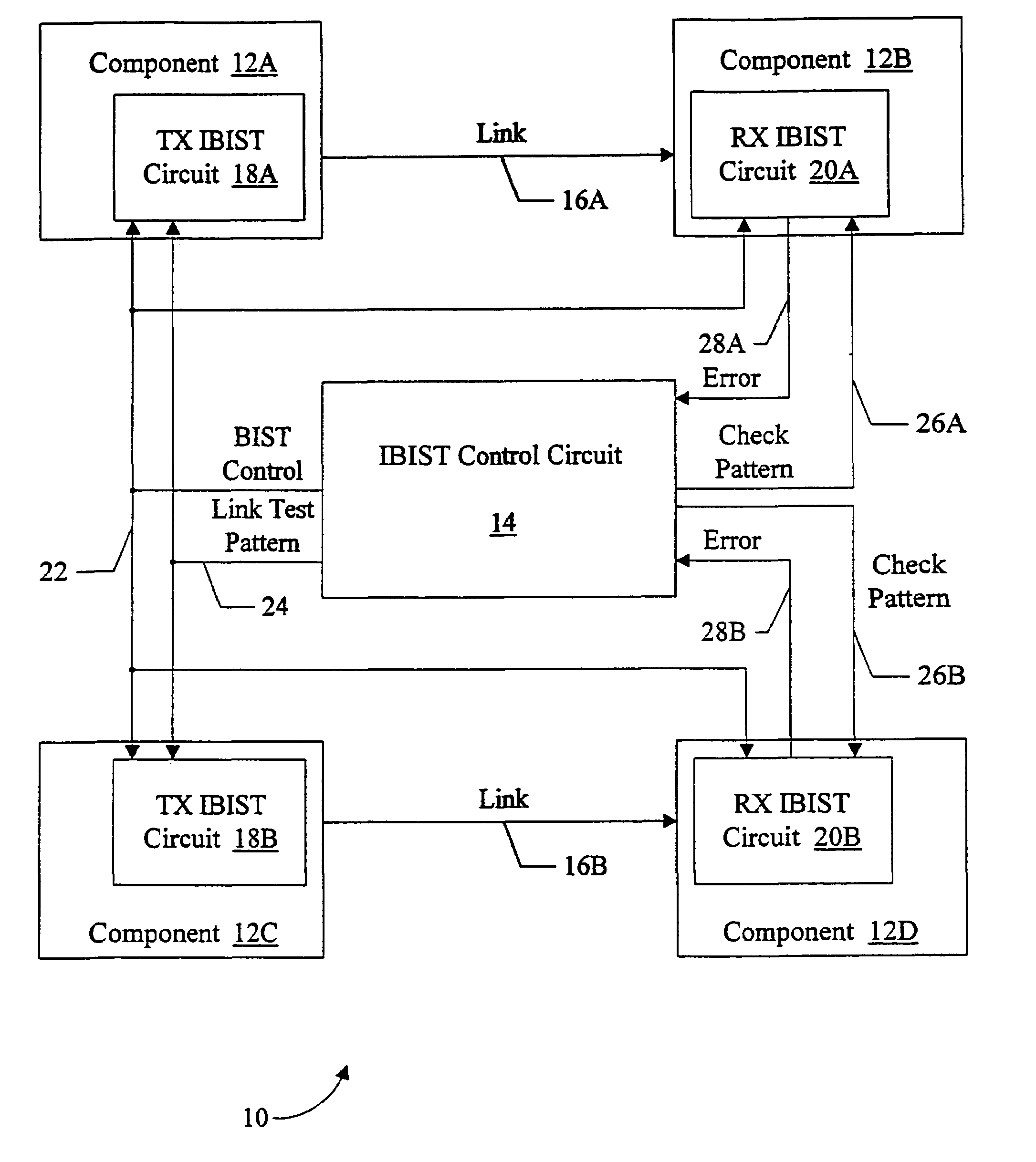
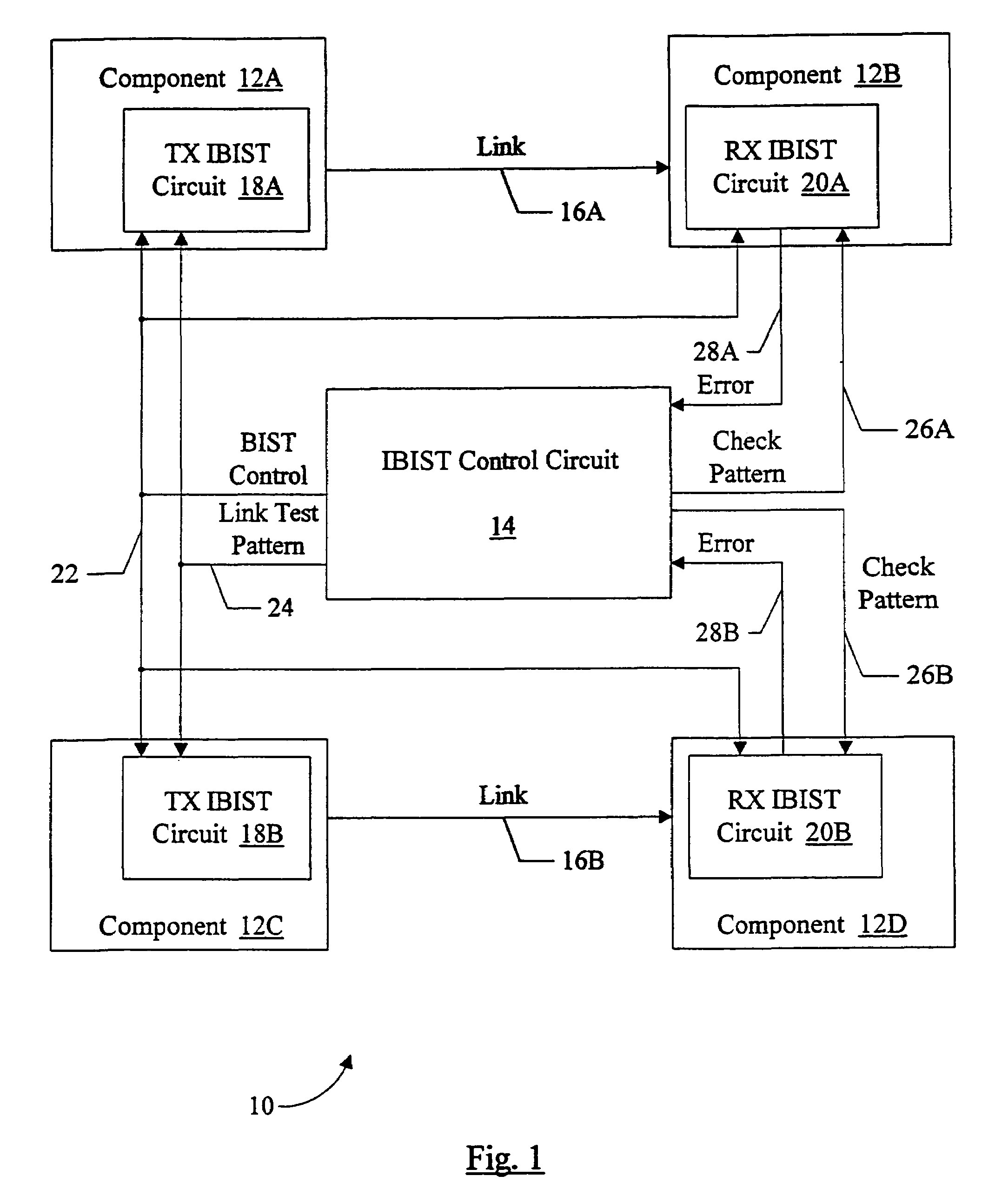
[0020]Turning now to FIG. 1, a block diagram of an exemplary system 10 is shown. Other embodiments are possible and contemplated. In the embodiment shown in FIG. 1, system 10 includes a plurality of components 12A–12D and an interconnect BIST (IBIST) control circuit 14. Component 12A is coupled to component 12B via a first source synchronous link 16A, and component 12C is coupled to component 12D via a second source synchronous link 16B. Component 12A includes a transmit IBIST (TX IBIST) circuit 18A and component 12C includes a TX IBIST circuit 18B. Component 12B includes a receive IBIST (RX IBIST) circuit 20A and component 12D includes an RX IBIST circuit 20B. IBIST control circuit 14 is coupled to provide BIST control signals on lines 22 to each of circuits 18A, 18B, 20A, and 20B. Additionally, IBIST control circuit 14 is coupled to provide a link test pattern on lines 24 to TX IBIST circuits 18A–18B. IBIST control circuit 14 is coupled to provide a first check pattern on lines 26...


PUM


Abstract

A system may perform interconnect BIST (IBIST) testing on source synchronous links. The system may perform, at normal operating frequency, a source synchronous link test that tests a victim line on the source synchronous link using a transition weave pattern. The transition weave pattern causes interaction between a data transition on the victim line, previous transitions on the victim line, and transitions on the other lines of the link (the “aggressor” lines). The interaction caused may be: (i) a first crossing pulse on the victim line; (ii) a second crossing pulse of the opposite polarity on each aggressor line concurrent with the first crossing pulse on the victim line; and (iii) a reflection in the opposite direction of the first transition of the first crossing pulse, wherein the reflection results from a previous transition on the victim line.

Description

BACKGROUND OF THE INVENTION[0001]1. Field of the Invention[0002]This invention is related to the field of computer systems and, more particularly, to verifying source synchronous links within computer systems.[0003]2. Description of the Related Art[0004]Integrated circuits (or “chips”) have included built-in self test (BIST) circuitry in order to ensure that the internal circuits of the chips are functioning properly. Generally, the BIST applies a series of test vectors to the inputs of the internal circuits and compares the outputs of the internal circuits to expected results. If the outputs differ from the expected results, then the BIST fails and the chip may include a faulty internal circuit. BIST may be run on the chip at the time of manufacture of the integrated circuit to screen out faulty parts before delivery to a customer, and may be run when the system including the chip is powered up (or at some other time as may be desired) to ensure that the chip is still functioning p...

Claims


Application Information

Patent Timeline
IPC IPC(8): G01R31/28G01R31/3185G06F11/267H04L1/24
CPCG01R31/3185G06F11/221H04L1/242
Inventor SMITH, BRIAN L.CHAKRABARTI, PRABHANSU
Owner ORACLE INT CORP
Learn More