Internal combustion engine exhaust gas purification system

a technology of exhaust gas purification system and internal combustion engine, which is applied in the direction of machines/engines, mechanical equipment, electric control, etc., can solve the problems of engine power decline, increased back pressure in the engine, and increased flow resistance of particulate filters

Active Publication Date: 2005-11-22
DENSO CORP
View PDF7 Cites 46 Cited by
  • Summary
  • Abstract
  • Description
  • Claims
  • Application Information

AI Technical Summary

Benefits of technology

[0011]In view of the foregoing problems, it is an object of the present invention to provide an exhaust-gas purification system of an internal combustion engine that can appropriately determine the regeneration timing of the particulate filter.

Problems solved by technology

If the amount of the collected particles excessively increases, flow resistance increases in the particulate filter and back pressure in the engine increases.
As a result, engine power decreases.
Otherwise, if the interval of the regeneration becomes long, the amount of the accumulated particles excessively increases, and the excessive amount of the accumulated particles may be rapidly burned in the regeneration process.
In this case, the particulate filter becomes excessively high in temperature, and the particulate filter may be broken.
However, it is difficult to precisely measure the particle accumulation amount in this exhaust gas purification system.
Therefore, a measurement error can be caused in the measurement of the particle accumulation amount due to the difference between an increasing characteristic of the particle accumulation amount and a decreasing characteristic of the particle accumulation amount.
The measurement error may affect the regeneration timing determination.
Furthermore, if the regeneration is not completed and terminated in the previous regeneration, the particles accumulated in the particulate filter are partially burned, and the measurement error may occur.

Method used


Image

  • Internal combustion engine exhaust gas purification system
  • Internal combustion engine exhaust gas purification system
  • Internal combustion engine exhaust gas purification system

Examples


first embodiment

[First Embodiment]

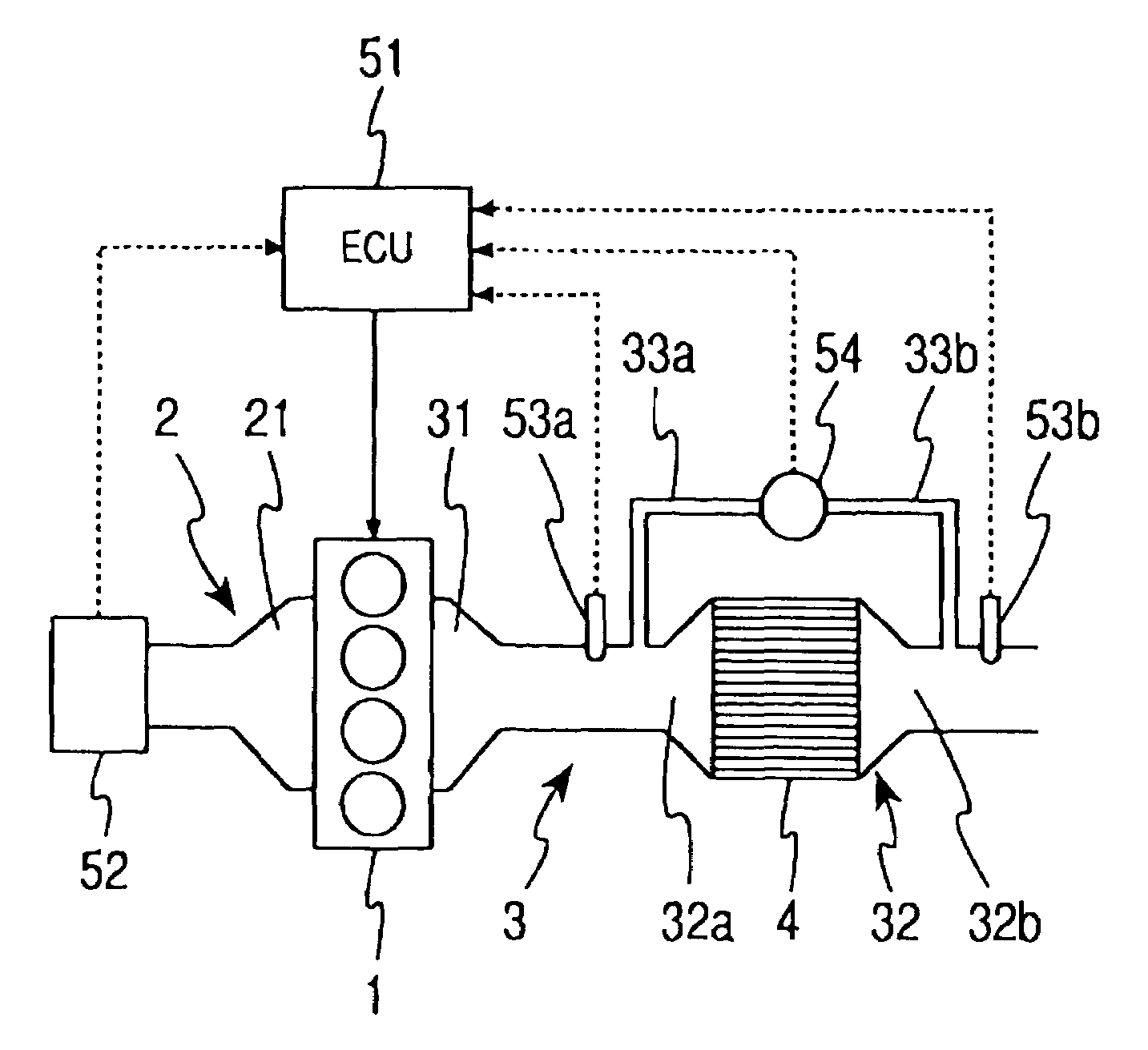
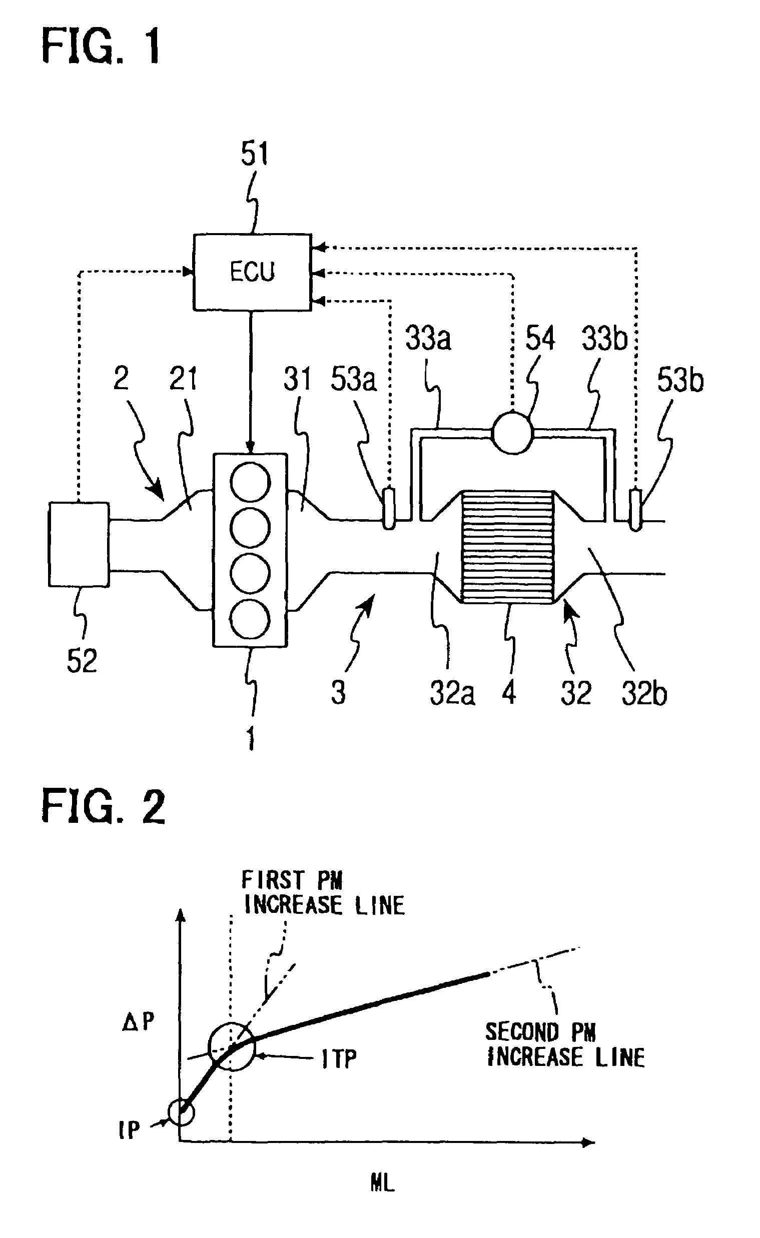
[0035]As shown in FIG. 1, a four-cylinder engine body (engine) 1 of a diesel engine is connected with an intake manifold 21, which is upstream of the engine with respect to the flow of air. The intake manifold 21 is the most downstream section of an intake passage 2. The engine body 1 is also connected with an exhaust manifold 31, which is downstream of the engine body 1. The exhaust manifold 31 is the most upstream section of an exhaust passage 3. A collecting section of the exhaust manifold 31 of the exhaust passage 3 is connected with a particulate filter 32.

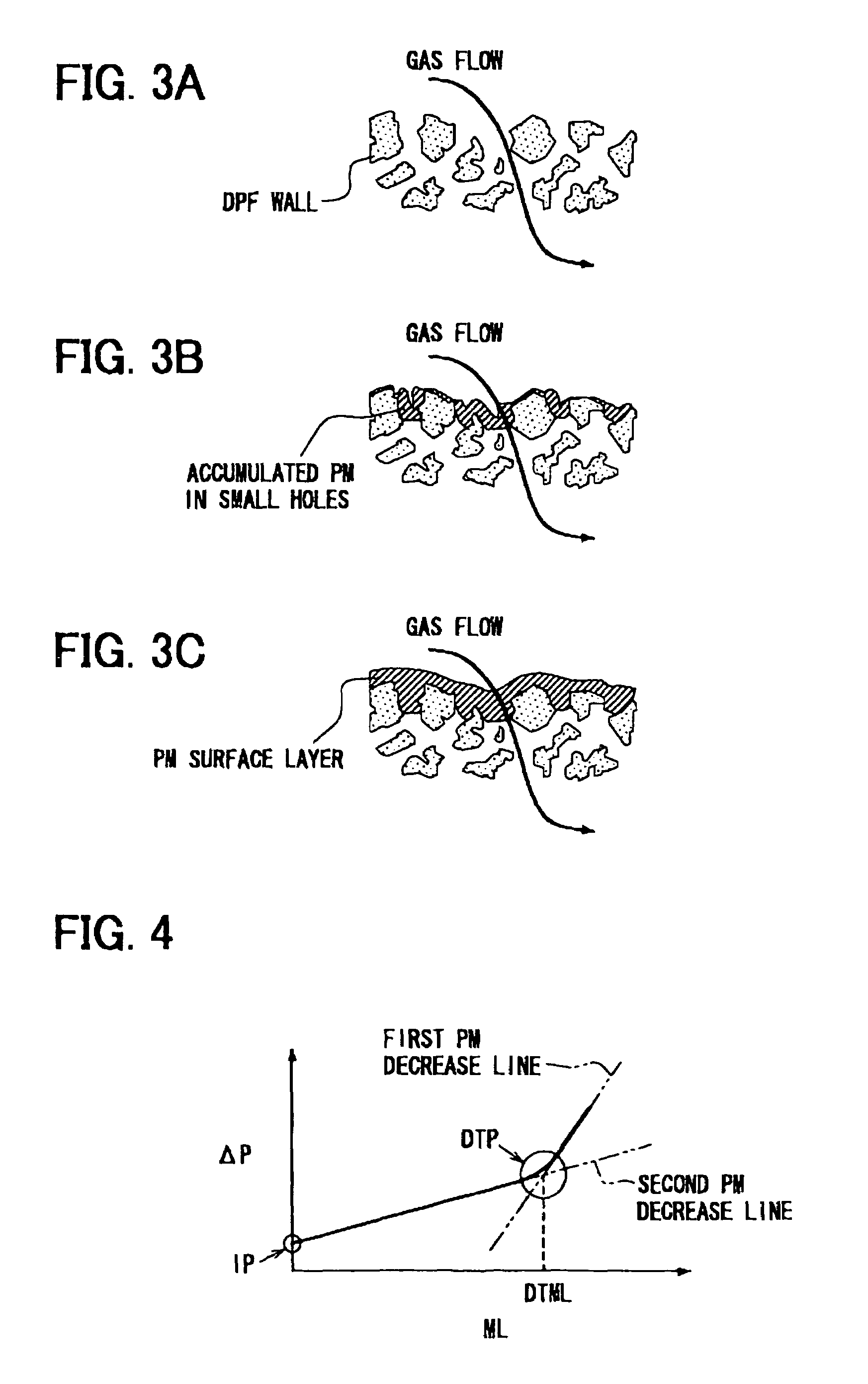
[0036]The particulate filter 32 is made of a porous ceramic, such as cordierite and silicon carbide. Honeycomb structural flow passages of the porous ceramic are partially closed, and the filter body 4 is constructed. Exhaust gas flows from cylinders of the engine body 1 to an intake port 32a. The exhaust gas flows from the intake port 32a to the filter body 4 of the particulate filter 32 and passes through ...

second embodiment

[Second Embodiment]

[0086]As shown in FIGS. 12 and 13, at step S201, previous operation statuses are stored. The previous operation statuses are the PM-accumulation amount ML, the integrated PM-combustion amount IMLcomb, a position of a characteristic equation flag FLG and the like, when the engine 1 was previously stopped. Here, the characteristic equation flag FLG has two positions (3 and 4).

[0087]Steps S202 and S208 are detecting units (exhaust particle detecting units) of the combusting condition of the accumulated particles PM. Steps S203 to S206 are determining units (regeneration determining units). At step S202, the condition of the particulate filter 32 is estimated in the same manner as that of step S107 in the first embodiment. At step S203, it is determined whether the PM-accumulation amount ML decreases or not, based on the result of step S202. At step S203, when a negative determination is made, the routine proceeds to step S204. Otherwise, when a positive determination...


PUM


Abstract

An amount ML of particles accumulated in small holes of a particulate filter is calculated in accordance with a pressure drop ΔP detected by a pressure sensor and a characteristic line. The characteristic line is defined by a first characteristic line and a second characteristic line, which is defined after exceeding a transition point TP. When the particles accumulated in the small holes are burned while remaining accumulated particles on the surface, the second characteristic line is shifted in a parallel fashion and compensated. Thus, the characteristic line is corrected so that the accumulation amount ML can be precisely calculated, even if particles accumulated in small holes are burned and the characteristic is changed.

Description

CROSS REFERENCE TO RELATED APPLICATION[0001]This application is based on Japanese Patent Application No. 2003-55087 filed on Mar. 3, 2003, and No. 2004-15555 filed on Jan. 23, 2004, the disclosures of which are incorporated herein by reference.BACKGROUND OF THE INVENTION[0002]1. Field of the Invention[0003]The present invention is related to an exhaust-gas purification system of an internal combustion engine, specifically a regeneration method of a particulate filter.[0004]2. Description of Related Art[0005]Recently, emission control has been required for internal combustion engines mounted in vehicles. Especially for a diesel engine, particles, such as soot (carbon black) and SOF (soluble organic fraction of particulate matter), contained in exhausted gas need to be removed in addition to CO, HC and NOx. Accordingly, a particulate filter is provided in an exhaust passage to collect exhausted particles in exhaust gas.[0006]Exhaust gas flowing into the particulate filter passes throu...

Claims


Application Information

Patent Timeline
Patent Type & Authority Patents(United States)
IPC IPC(8): F01N3/023F01N9/00F01N11/00F01N3/02F02D45/00
CPCF01N3/023F01N9/002F01N11/002Y02T10/47Y02T10/40
Inventor SAITO, MAKOTOYAHATA, SHIGETOTOCHIKAWA, KAZUHARU
Owner DENSO CORP
Why Eureka
Try Eureka