Charging of devices by microwave power beaming

Inactive Publication Date: 2005-11-22
NASA
View PDF17 Cites 806 Cited by
  • Summary
  • Abstract
  • Description
  • Claims
  • Application Information

AI Technical Summary

Benefits of technology

[0012]According to another aspect of the invention, each individual microwave array emitter produces energy at a frequency close to, but different from that produced by any other microwave array emitter in the system. This reduces loss of energy in sidelobes, and minimizes interference issues.
[0013]According to another aspect of the invention, the power transmitter includes backscatter detectors for detecting backscatter ene

Problems solved by technology

Frequencies higher than 10 GHz can be employed (e.g., millimeter wave), b

Method used


Image

  • Charging of devices by microwave power beaming
  • Charging of devices by microwave power beaming
  • Charging of devices by microwave power beaming

Examples


Example

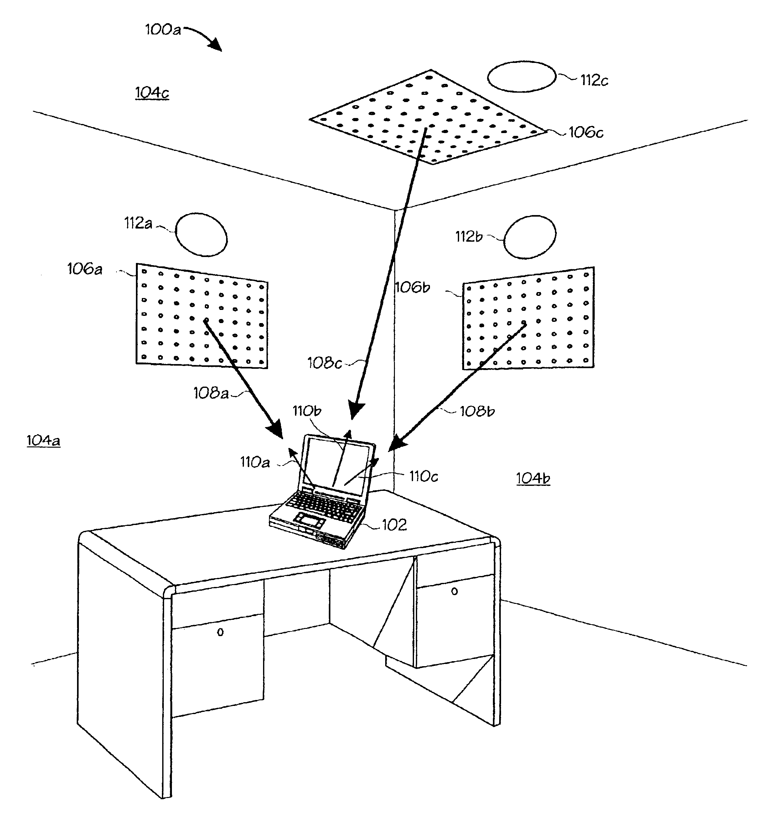
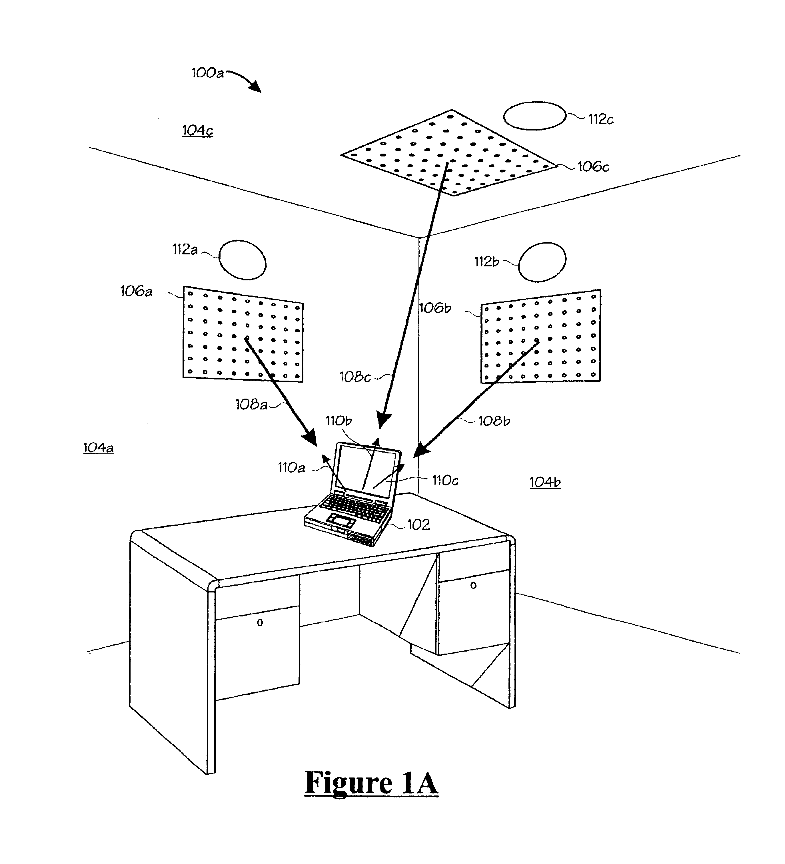
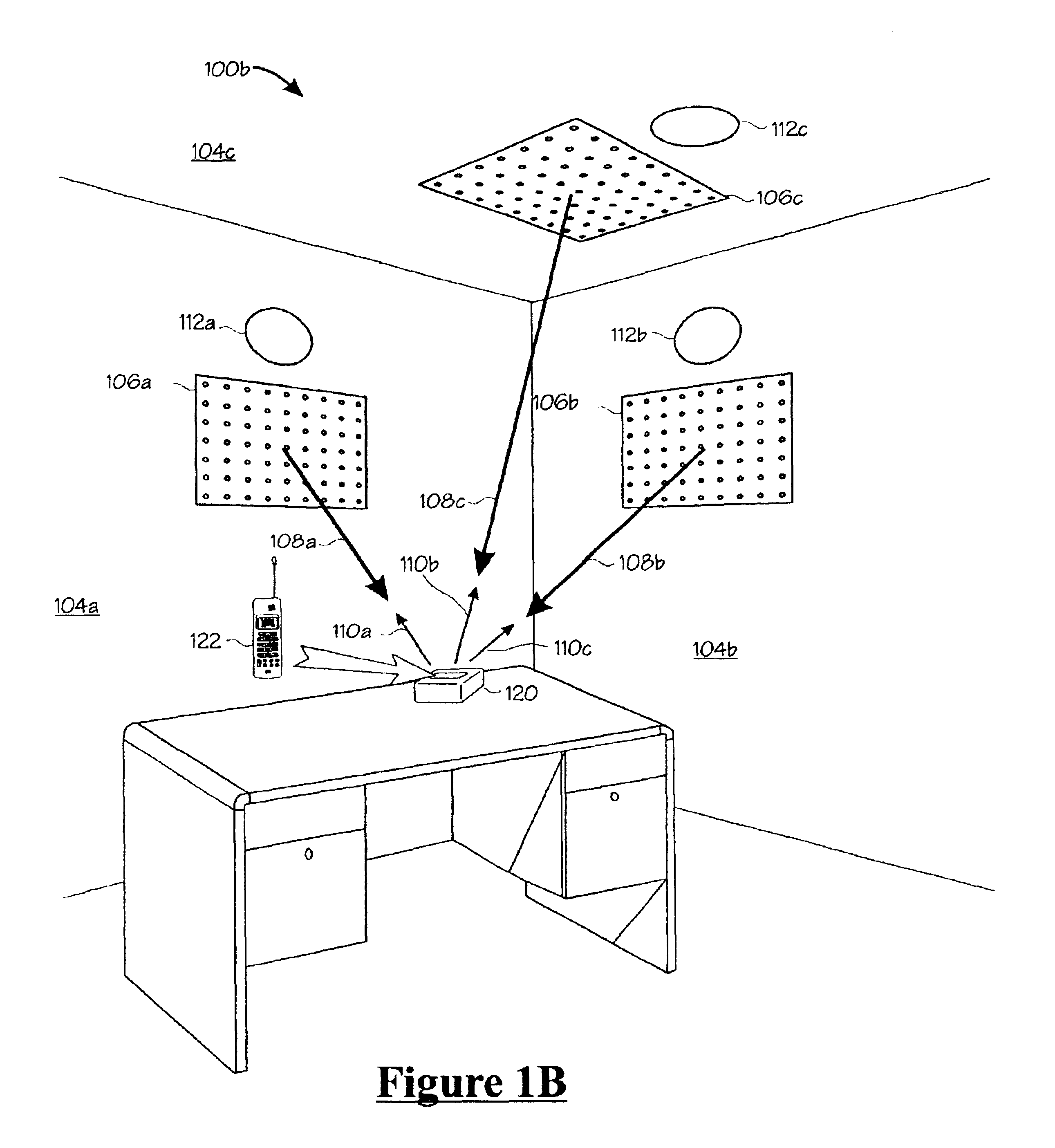
[0022]The present inventive technique provides for charging and / or powering of an electrical / electronic device using microwave energy. One or more adaptive-phased arrays are used to focus one or more “rectennas” (rectifying antennas) disposed within the consumer device. Microwave energy reaching the rectenna(s) is converted into DC electrical energy that is used to charge a battery or other energy storage device within the consumer device. The DC electrical energy can also be used to provide primary power for the consumer device while the battery or storage device is being charged.

[0023]FIG. 1A is a view of a system 100a for direct microwave charging of an electrical / electronic device 102, wherein a plurality of adaptive-phased array microwave emitters 106a, 106b and 106c are disposed on walls 104a, 104b and ceiling 104c, respectively of a room in which the electrical / electronic device 102 resides. Pilot beams 100a, 100b, 110c from the electrical / electronic device 102 permit the sys...


PUM


Abstract

A system for providing wireless, charging power and/or primary power to electronic/electrical devices is described whereby microwave energy is employed. Microwave energy is focused by a power transmitter comprising one or more adaptively-phased microwave array emitters onto a device to be charged. Rectennas within the device to be charged receive and rectify the microwave energy and use it for battery charging and/or for primary power. A locator signal generated by the device to be charged is analyzed by the system to determine the location of the device to be charged relative to the microwave array emitters, permitting the microwave energy to be directly specifically towards the device to be charged. Backscatter detectors respond to backscatter energy reflected off of any obstacle between the device to be charged and the microwave array emitters. Power to any obstructed microwave array emitter is reduced until the obstruction is removed. Optionally, data can be modulated onto microwave energy beams produced by the array emitters and demodulated by the device, thereby providing means of data communication from the power transmitter to the device. Similarly, data can be modulated onto the locator signal and demodulated in the power transmitter, thereby providing means of data communication from the device to the power transmitter.

Description

ORIGIN OF THE INVENTION[0001]The invention described herein was made by an employee of the United States Government and may be manufactured and used by or for the Government for Government purposes without the payment of any royalties thereon or therefore.TECHNICAL FIELD[0002]The present invention relates generally to wireless charging and powering of battery-powered electrical / electronic devices, including consumer devices.BACKGROUND ART[0003]A recent trend in consumer electronic devices is small, battery operated devices with on-board rechargeable batteries that are recharged by using a small, external charging adapter. These consumer devices can be, e.g., cell phones, personal digital assistants (PDAs), personal stereo devices (e.g., “Walkman”, or MP3 Player), laptop computers, calculators, pagers, etc. Typically, the charging adapters for these devices are wall-plug AC adapters that provide bulk, low-voltage AC or DC charging power to the consumer device for operating the device...

Claims


Application Information

Patent Timeline
IPC IPC(8): H01M10/46H01M10/42H02J17/00
CPCH02J17/00H01M10/46H02J50/20H02J50/40H02J50/90Y02E60/10H02J50/70H02J50/80
Inventor LANDIS, GEOFFREY A.
Owner NASA
Why Eureka
Try Eureka